Connecting up
5.7 Functional ground
SCALANCE XR-300WG
Operating Instructions, 05/2017, C79000-G8976-C454-01
45
Assignment of the connecting cable
The connecting cable listed in the "Accessories" section has the following pin assignment:
Pin assignment of the RJ-11 plug
Pin assignment of the D-sub female con-
nector
2 - TD (Transmit Data)
4 SG (Signal Ground) -
Note
Pin assignment of the RJ-11 jack on the device
The RJ
-11 jack on the device has a pinout to match the RJ-11 plug of the connecting cable
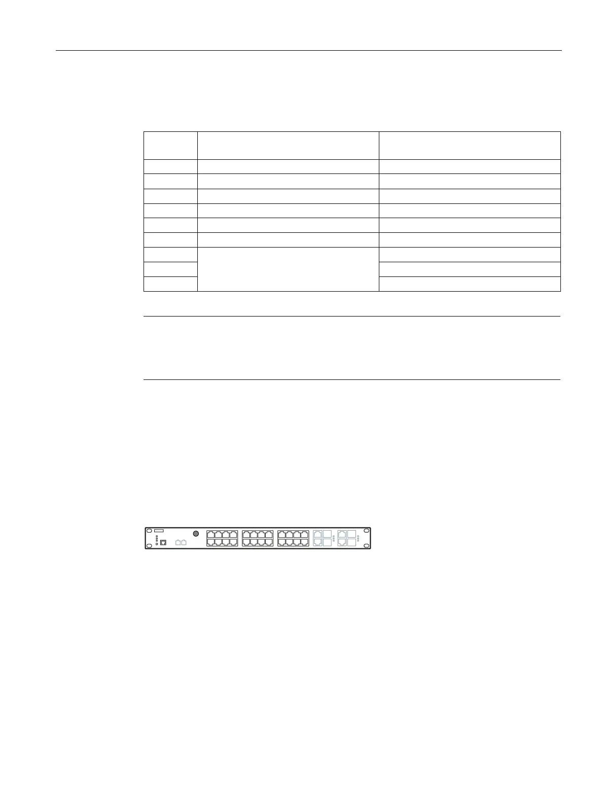
Functional ground
Grounding options
Grounding (functional ground) is via the mounting bracket on the device or via the grounding
screw the front of the device.
Figure 5-4 Position of the grounding screw on the SCALANCE XR-300WG
With 240 VAC variants the device is grounded via the power cable.
EMC disturbances are diverted to ground via the functional ground. This ensures the
immunity of the data transmission.
The functional ground must be implemented with low impedance. The connection of the
functional ground must be established directly on the mounting plate or the DIN rail terminal.
 Loading...