Mounting and connecting
3.1 Preparations
Basic Panels 2nd Generation
24 Operating Instructions, 10/2016, A5E33293231-AB
Making the mounting cutout
Note
Stability of the mounting cutout
The material in the area of the mounting
cutout must provide sufficient strength to guarantee
lasting and safe mounting of the HMI device.
To achieve the degrees of protection described below, it must be ensured that deformation
of the material cannot occur due to the force of the mounting clips
or operation of the device.
The degrees of protection of the HMI device can only be guaranteed if the following
requirements are met:
● Material thickness at the mounting cutout for a protection rating of IP65 or Front face only
Type 4X/Type 12 (indoor use only): 2 mm to 6 mm.
● Permitted deviation from plane at the mounting cutout: ≤ 0.5 mm
This condition must be met for the mounted HMI device.
● Permitted surface roughness in the area of the mounting seal: ≤ 120 µm (R
z
120)
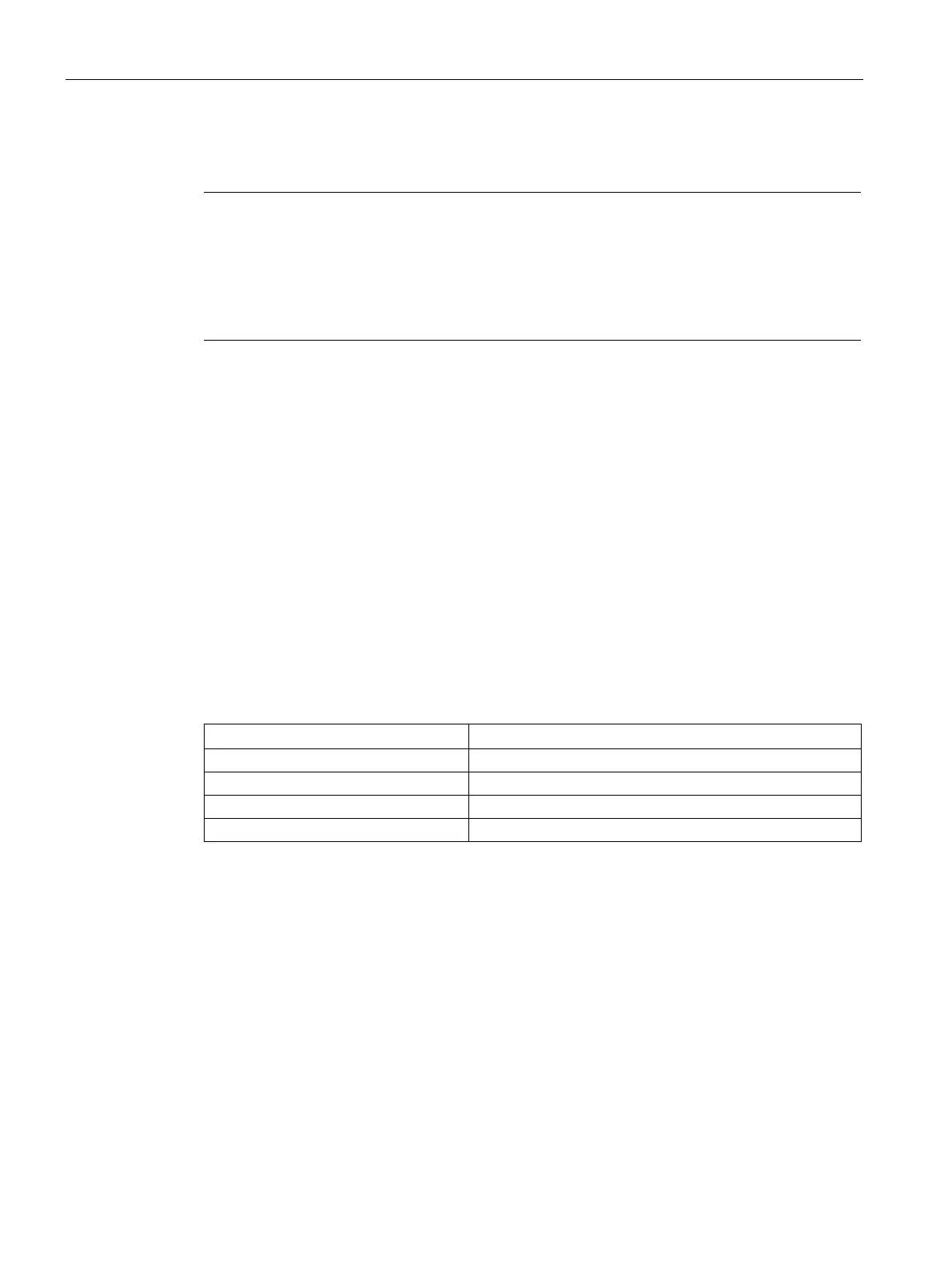
The mounting cutouts of the Basic panels are compatible with the mounting cutouts of the
following SIMATIC HMI devices:
Mounting cutout Basic Panel
Compatible with the mounting cutouts of the HMI device
KTP700 Basic, KTP700 Basic DP
KTP600 Basic color PN; TP700 Comfort
KTP1200 Basic, KTP1200 Basic DP
 Loading...