09/02 Diagnostics
CP 243-1
J31069-D0428-U001-A1-7618
59
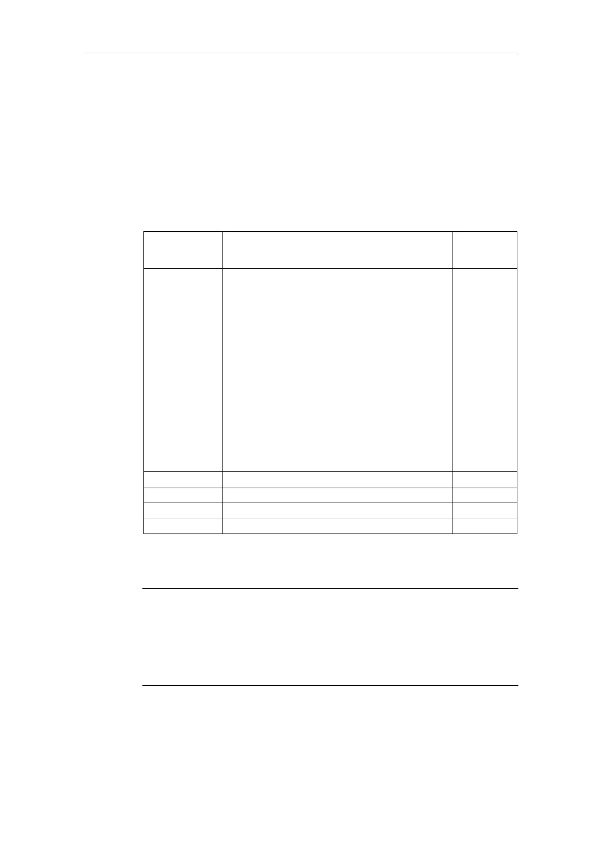
• Reading out of the NPB memory area:
In the bytes 46 to 49 of the SM area currently being used for a CP 243-1, a
pointer is located at the memory area in which the configuration data of the CP
243-1 are stored. If you raise this pointer by 108, you fill find the NPB memory
area in which the TCP/IP configuration parameters currently being used by the
CP 243-1 are stored, provided the CP 243-1 was correctly configured and that
at least one cycle of the user program has been run through. The NPB does not
contain valid values if the configuration is faulty. The following table shows the
structure of these memory areas.
Byte offset in
variables
memory
Meaning Format
108 - 109 Common flag byte
Bit [0] Duplex Mode
0: Half Duplex
1: Full Duplex
Bit [1] Data Rate
0: 10 Mbit/s
1: 100 Mbit/s
Bit [2] Auto Negotiation
0: Auto Negotiation not enabled
1: Auto Negotiation enabled
Bit [3] BOOTP
0: Network parameters from configuration
1: Network parameters via BOOTP
Bit [4] - Bit [15]: Reserved
2 bytes hex
110-113 Current IP address 4 bytes hex
114- 117 Current subnet mask 4 bytes hex
118-121 IP address of the Gateway currently in use 4 bytes hex
122-127 MAC address 6 bytes hex
Table 14: Structure of NPB memory areas
• LED indicators (see Chapter 2.5)
Note
If there is a sudden termination of a CP 243-1 with active client connections (e.g.
due to power failure) while the server continues running, the server may not recog-
nize this interruption in the connection. If the client then attempts to reconnect, a
system-related waiting period equal to the configured Keep Alive time may arise,
beginning when the CP 243-1 is switched on again, until all connections are re-
established.