Design and Functional Principle
17
SIP ART PS2 Manual
A5E00074631-01
8
9
6.2
6.1
10
3
7
-- --
++
1
10
138238 9
2121
45
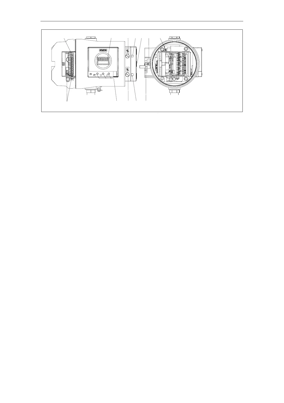
1 Input: Supply air 7 Transmission ratio selector
2 Output: Actuating pressure Y1 (only possible with positioner open)
3 Display 8 Adjusting wheel slip clutch
4 Output: Actuating pressure Y2
*)
9 Terminals standard controller
5 Operating keys 10 Terminals options modules
6.1 Restrictor Y1 12 Safety catch
6.2 Restrictor Y2
*)
*)
in double--acting actuators
Figure 2-2 View of the explosion proof version of the positioner
2.2.1 Motherboard
The motherboard contains all the electronic elements such as the CPU,
memory, A/D converter. It also contains the display and the operating
keys.
In addition, the terminal strips for connecting the options modules are
also on the motherboard.
2.2.2 Electrical Connections
The terminals of the standard controller, the J
y
- and alarm-option mo-
dule are arranged at the left--hand front edges and offset against each
other in staircase form.
A module cover protects the modules from being pulled out and pre-
vents incorrect installation.
 Loading...