EasyManuals Logo
Home>Siemens>Control Unit>SIPROTEC 4 7XT7100-0 A00/EE Series

Siemens SIPROTEC 4 7XT7100-0 A00/EE Series User Manual

Siemens SIPROTEC 4 7XT7100-0 A00/EE Series
88 pages
To Next Page IconTo Next Page
To Previous Page IconTo Previous Page
Page #40 background imageLoading...
Page #40 background image
38 SIPROTEC 4/5, Injection Unit 7XT71, Product Information
C53000-B1174-C128-7, Edition 09.2016
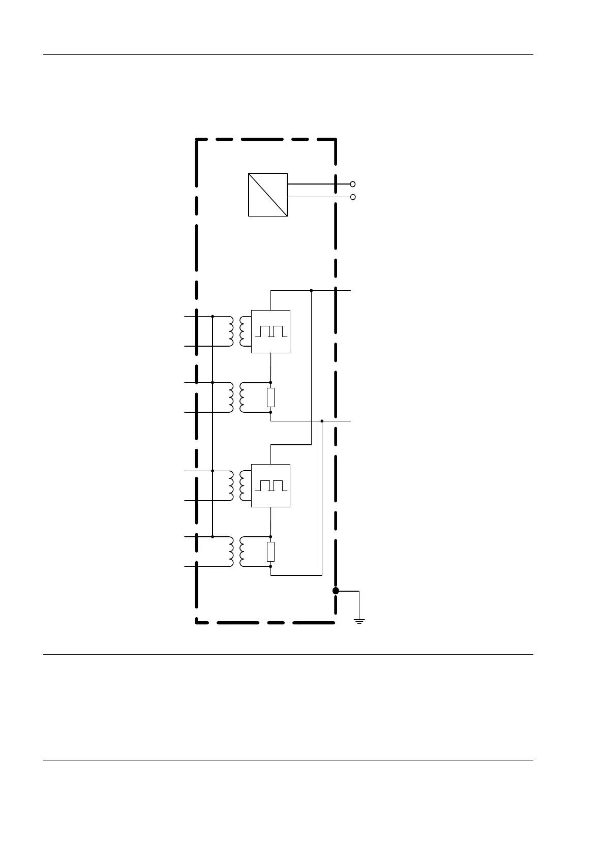
13 Block Diagram
Fig. 13-1 Block Diagram of Injection Unit 7XT71
7XT71
1
2
7
11
9
13
8
10
12
14
~
=
17
18
U
Steuer
V
Control
U
Steuer
V
Control
U
Mess
V
Meas
U
Mess
V
Meas
+
U
H
(+U
aux
)U
L1
(U
a
)
DC AC
-U
H
(-U
aux
)U
L2
(U
b
)
NOTE
The voltage between terminal 1 and terminal 2 (and to ground) must not exceed AC
300 V.
Non-observance can result in material damage.
Apply suitable protection measures.

Questions and Answers:

Question and Answer IconNeed help?

Do you have a question about the Siemens SIPROTEC 4 7XT7100-0 A00/EE Series and is the answer not in the manual?

Siemens SIPROTEC 4 7XT7100-0 A00/EE Series Specifications

General IconGeneral
BrandSiemens
ModelSIPROTEC 4 7XT7100-0 A00/EE Series
CategoryControl Unit
LanguageEnglish

Related product manuals