40 SIPROTEC 4/5, Injection Unit 7XT71, Product Information
C53000-B1174-C128-7, Edition 09.2016
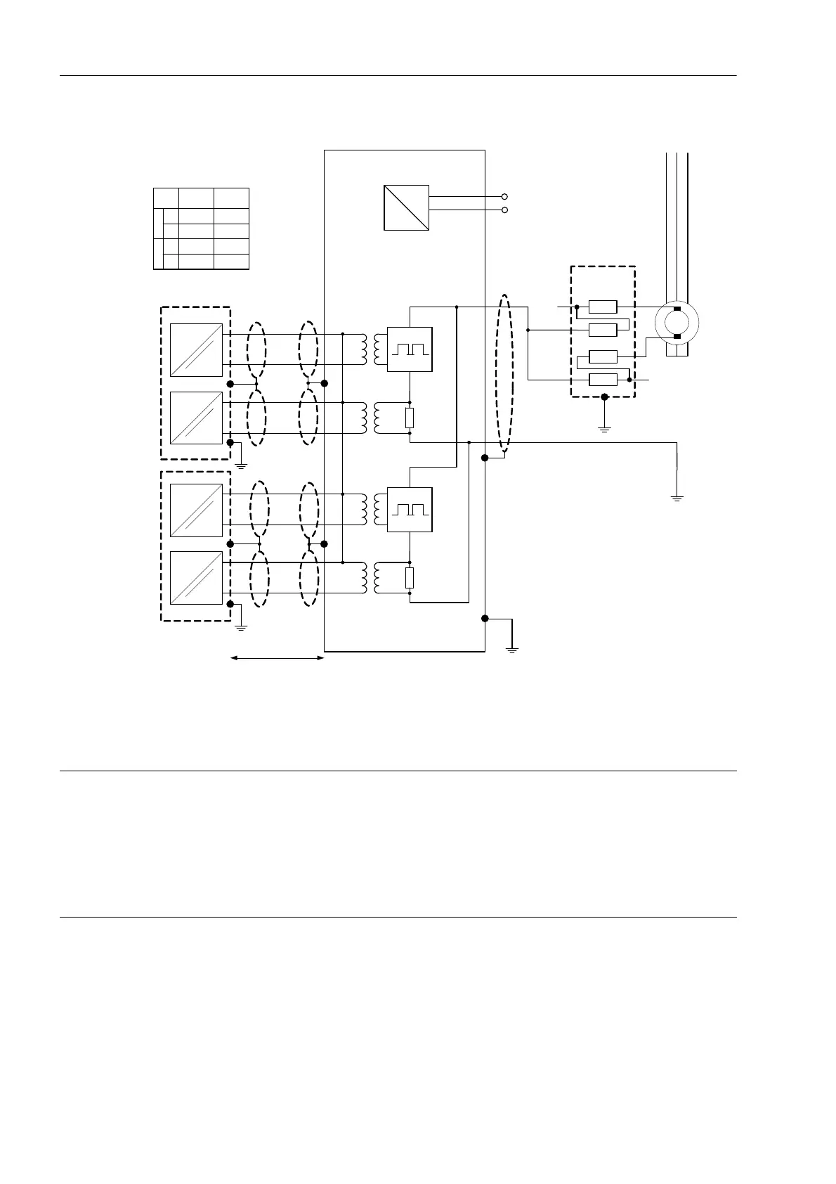
Fig. 14-2 Connection Diagram for excitation voltages < DC 1200 V
7UMxx
7UMxx
L1 L2 L3
1
2
7
11
9
13
8
10
12
14
~
=
17
18
Erde der Generatorwelle
Rotor Ground
MU
1
MU
2
MU
1
MU
2
A6
A11
A3
B14
B11
B18
A
B
C
D
K13
K14
K15
K16
U
Mess
V
Meas
U
Mess
V
Meas
U
Steuer
V
Control
U
Steuer
V
Control
Leitungslänge < 10 m
cable lenght < 10 m (30 feet)
+U
H
(+ U
aux
)
DC
20 kΩ
20 kΩ
7XT71
20 kΩ
20 kΩ
7XR6004
a b c
-U
H
(-U
aux
)
U
L1
(U
a
)
AC
U
L2
(U
b
)
A
B
C
D
K13
K14
K15
K16
B13
C3
B14
C4
7UM62
7UM85
(IO210 )
Schutzger ätanschlusse
Protection relay connections
MU1MU2
NOTE
The voltage between terminal 1 and terminal 2 (and to ground) must not exceed AC
300 V.
Non-observance can result in material damage.
✧ Apply suitable protection measures.
 Loading...