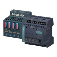
Description, device design, dimension drawing
2.4 Status displays and signaling
Selectivity modules
Manual, 12.2014, C98130-A7579-A1-1-7629
13
Status displays and signaling
6EP1961-2BA11
6EP1961-2BA21
6EP1961-2BA31
6EP1961-2BA41
Group signaling contact
(13-14 or 11-12-14)
④
floating relay contact (NO
contact),
contact rating:
floating relay contact
(changeover contact),
contact rating:
-
Status output (S) ④
- - Non-floating 24 V DC output,
Remote reset input (RST)
④
- Non-floating
24 V DC input
Non-floating
24 V DC input
Figure 2-4 Operating displays and signaling (SITOP select and SITOP PSE200U)
The operating state of the outputs is displayed using multi-color LEDs at the front of the
device. Symbols indicate the significance of each LED, which are listed in the following table.

 Loading...


