EasyManua.ls Logo

Simplex 4903 User Manual

Simplex 4903
12 pages
To Next Page IconTo Next Page
To Previous Page IconTo Previous Page
Page #2 background image
FLASHER RATING CHART
TYPE PRODUCT ID ** EFFECTIVE INTENSITY FLASH RATE
4904-9104 100 CANDELA -
1 PER SECOND
4904-9105 AT 24VDC
4904-9106 88/200mA
(NOMJPEAK)
4903-9151
8.4 CANDELA -
1 PER SECOND
1 POVAC 4903-9154
AT 12OV 60Hz
FLASHER 4904-9151
120mA
4904-9152
4904-9153
I
I I I
I
** PER ULI 1638 STANDARD.
installation Procedure
Assemble Lens (if Required) - INCANDESCENT UNITS ONLY
1. Attach the reflector (A) to the Lamp Printed Circuit (PC) Board (B) by lining up
the reflector’s cut-outs (C) with the lamps (D) and then pushing the reflector
over the lamps. See Figure 2.
NOTE: Make sure that the reflector’s flanges face towards the lamp board’s
component surface.
2. Insert the Lamp PC Board with reflector inside the lens (E) by placing the
Lamp PC Board behind the lens’ two bottom tabs (F) and then snapping the
Lamp Board onto the top tab (G). See Figure 2.
NOTE: Make sure that the reflector is wrinkle-free and over the lamps.
INCANDESCENT RATING CHART
TYPE
24VDC
PRODUCT ID ** EFFECTIVE INTENSITY
4903-9001 0.5 CANDELA
0.32 CANDELA
4903-9102
AT 24VDC
AT 19.6VDC
4904-9001 80mA
4904-9002
4904-9003
120VAC
4903-9051 0.32 CANDELA
-
4903-9152
AT 12OV 60Hz
4904-905 1 80mA
4904-9052
4904-9053
** PER ULI 1638 STANDARD
2
Question and Answer IconNeed help?

Do you have a question about the Simplex 4903 and is the answer not in the manual?

Simplex 4903 Specifications

General IconGeneral
BrandSimplex
Model4903
CategoryFire Alarms
LanguageEnglish

Summary

Flasher Unit Assembly and Specifications

Flasher Unit Lens Assembly Procedure

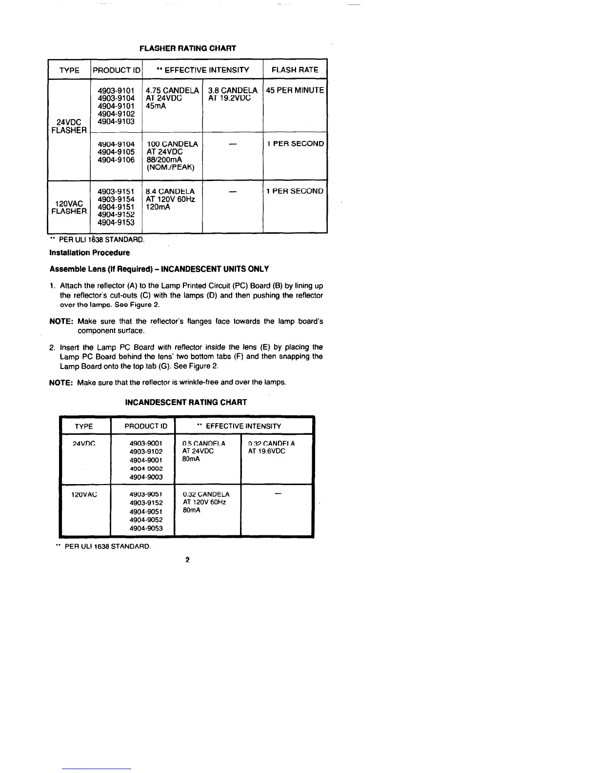
Steps for assembling the lens and reflector for flasher units.

Flasher Unit Light Distribution Patterns

Diagram illustrating light output percentages at various viewing angles for flasher units.

Flasher Rating Chart Details

Table detailing effective intensity and flash rates for different flasher unit models.

Incandescent Unit Assembly and Specifications

Incandescent Unit Lens Assembly Procedure

Steps for assembling the lens and reflector for incandescent units.

Incandescent Unit Light Distribution Patterns

Diagram showing light output percentages for incandescent unit viewing angles.

Incandescent Rating Chart Details

Table detailing effective intensity for incandescent unit models.

Unit Base Attachment and Wiring Diagrams

Attaching Lens Assembly to Base Unit

Connecting the assembled lens unit to the audible/visible or visible only base.

Flasher Unit Wiring Diagrams (21-28VDC)

Wiring diagrams for flasher units with notification appliances and speakers at 21-28VDC.

Flasher Unit Wiring Diagrams (120V)

Wiring diagrams for 120V flasher units with speakers and notification appliances.

Incandescent Unit Wiring Diagrams (21-28VDC)

Wiring diagrams for incandescent units with notification appliances and speakers at 21-28VDC.

Incandescent Unit Wiring Diagrams (120V)

Wiring diagrams for 120V incandescent units with speakers and notification appliances.

Final Mounting Procedures

Mounting 4903 Audible/Visible Units

General procedure for mounting 4903 A/V units and specific notification appliances.

Surface/Retrofit and 4904 Visible Mounting

Procedures for surface/retrofit mounting and mounting 4904 Visible Only units.

Related product manuals