Mount Audible/Visible or Visible Only Assembly to Electrical Back BOX
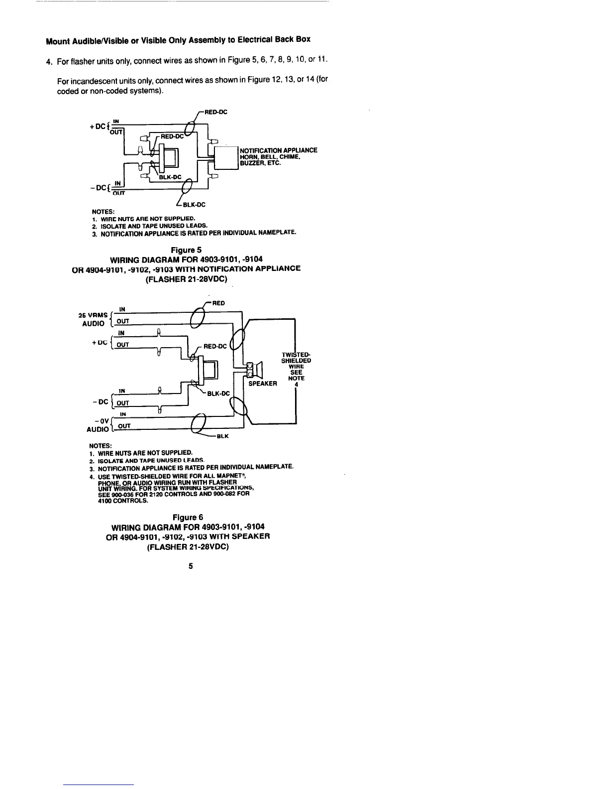
4. For flasher units only, connect wires as shown in Figure 5,6,7,6,9, 10, or 11.
For incandescent units only, connect wires as shown in Figure 12,13, or 14 (for
coded or non-coded systems).
NOTlFlCATlON APPLIANCE
HORN. BELL, CHIME,
BUZZER, ETC.
L ELK-DC
NOTES:
1. WIRE NUTS ARE NOT SUPPLIED.
2. ISOLATE AND TAPE UNUSED LEADS.
3. NOTIFICATION APPLIANCE IS RATED PER INDIVIDUAL NAMEPLATE.
Figure 5
WIRING DIAGRAM FOR 4903-9101, -9104
OR 4904-9101, -9102, -9103 WITH NOTIFICATION APPLIANCE
(FLASHER 21-28VDC)
-DC LOUT
I
IN
Y
A
//
I
NOTES:
1. WIRE NUTS ARE NOT SUPPLIED.
2. ISOLATE AND TAPE UNUSED LEADS.
3. NOTlFlCATlON APPLIANCE IS RATED PER INDIVIDUAL NAMEPLATE.
4. USE TWISTED-SHIELDED WIRE FOR ALL MAPNET?
PHONE, OR AUDIO WIRING RUN WlTH FLASHER
UNlT WIRING. FOR SYSTEM WIRING SPECIFICATIONS.
SEE 900-036 FOR 2120 CONTROLS AND 900-0S2 FOR
4100 CONTROLS.
Figure 6
WIRING DIAGRAM FOR 4903-9101, -9104
OR 4904-9101, -9102, -9103 WITH SPEAKER
(FLASHER 21-28VDC)

 Loading...