2-6
Installing the SMC6624M Switch
Installation Procedures
Installing the SMC6624M
Switch
2. Install Modules (optional)
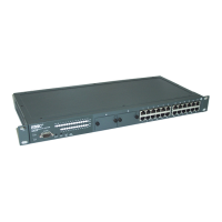
Install a module into one or both of the slots as shown in the illustration below.
For installation details, see the instructions in the Installation Guide that
comes with the module.
The slot cover can be removed with either a flat-bladed or Torx T-10 screw-
driver. Keep the slot cover for future use.
Module
Notes
■ Any of the supported Gbps (gigabit) and 100 Mbps modules can be
installed in the slots in the SMC6624M. See “Supported Modules” below.
■ Make sure the modules are fully installed and that you screw in
the retaining screws to secure the modules in place.
■ If you do not install a module in one or both of the slots, make sure that
the slot cover plate(s) is still attached over the slot for safe operation and
proper switch cooling.
■ The modules can be installed while the switch is powered on. Once the
modules are installed, reset the switch by pressing the Reset
button on the front of the switch. This resets/reboots the switch which
initializes and activates the module. Until the switch is reset/rebooted, the
module will not be operational. If you install the modules when the switch
is powered off, powering on the switch after the installation will initialize
the modules.
■ The modules can operate only at full duplex. Half duplex operation is not
supported.
Supported Modules. When this manual was printed, the supported
modules include the following:
■ 1000Base-SX module (SMC6624GSSC)
■ 1000Base-LX module (SMC6624GLSC)
■ 100/1000Base-T module (SMC6624GT)
■ 100Base-FX module (SMC6624FMSC)
■ Stacking module (part of the SMC6624M Gigabit Stacking Kit - SMC6624S)
Note The 1000Base-SX, and 1000Base-LX modules are Class 1 Laser Products
(Laser Klasse 1). They comply with IEC 825-2: 1993.
 Loading...