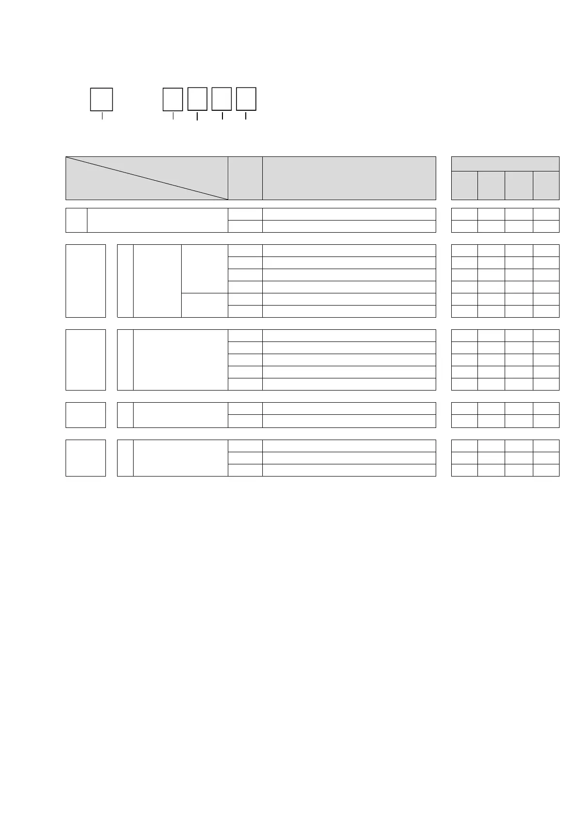
How to Order of Pilot Valve Assembly
AV 2 0 - 1 G B A
Symbol
Description
Applicable size
AV
2000
AV
3000
AV
4000
AV
5000
❶
Body size
2 AV2000-A, AV3000-A
● ● ― ―
4 AV4000-A, AV5000-A
― ― ● ●
+
❷
a
d
Rated coil
voltage
AC
(50/60Hz)
1 AC100V
● ● ● ●
2 AC200V
● ● ● ●
3 AC110V [AC115V]
*1
● ● ● ●
4 AC220V [AC230V]
*1
● ● ● ●
DC
5 DC24V
● ● ● ●
6 DC12V
● ● ● ●
+
❸
e
Electrical entry
G Grommet(Lead wire length: 300mm)
● ● ● ●
D Type D(DIN terminal/With connector)
● ● ● ●
Y Type Y(DIN terminal/With connector)*
2
● ● ● ●
DO Type D(DIN terminal/Without connector)
● ● ● ●
YO Type Y(DIN terminal/Without connector)
● ● ● ●
+
❹
f
Light/
surge voltage suppressor
NIL None
● ● ● ●
With light/surge voltage suppressor
〇
*3
〇
*3
〇
*3
〇
*3
+
❺
g
Manual override
NIL Non-locking push type
● ● ● ●
B Push-turn locking slotted type
● ● ● ●
C Push-turn locking lever type
● ● ● ●
*1 The 110 VAC and 115 VAC are interchangeable. The 220 VAC and 230 VAC are interchangeable as well.
The allowable voltage fluctuation is -15% to +5% of the rated voltage for the 115 VAC or 230 VAC.
*2 Type “Y” is a DIN terminal conforming to EN-175301-803C (former DIN43650C).
*3 When the electrical entry is DO or YO, light/surge voltage suppressor cannot be selected.
-20-

 Loading...

