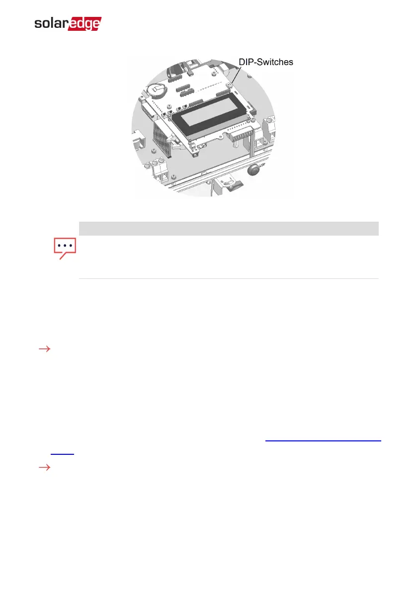
Figure 28: RS485 termination switch
NOTE
Only the first and last SolarEdge devices in the chain should be terminated.
The other inverters in the chain should have the termination switch OFF
(down position).
11. If not using surge protection, connect the grounding wire to the first inverter in the
RS485 chain; make sure the grounding wire is not in contact with other wires. For
inverters with a DC Safety Unit, connect the grounding wire to the grounding bus-
bar in the DC Safety Unit.
To connect to the monitoring platform:
1. Designate a single inverter as the connection point between the RS485 bus and the
SolarEdge monitoring platform. This inverter will serve as the master inverter.
2. Connect the master to the SolarEdge monitoring platform via the LAN or ZigBee or
cellular communication option.
3. Install an RS485 Plug-in in every EV Charging single phase inverter , refer to the
'Installing the RS485 Expansion Module' chapter in the RS485 Expansion Kit Installation
Guide and to configure the RS485 bus refer to the following sections.
To configure the RS485 communication bus:
All inverters are configured by default as slaves. If reconfiguration is required:
Chapter 7: Setting Up Communication 77
Three Phase System Installation Guide MAN-01-00057-4.1
 Loading...