1
Setting Up ZigBee Communication between
SolarEdge Devices
This document describes how to install and set up ZigBee communication between several SolarEdge devices (inverters and Safety
and Monitoring Interfaces (SMI)).
What’s in the Box
Make sure all of the items listed below are included in your box:
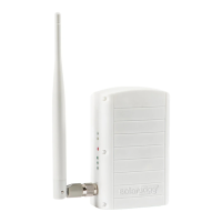
1 x ZigBee coordinator (master) module OR 1 x ZigBee router (slave) module
8.5” RG-174 RF cable, RP-SMA connectors
2.11” Helical whip 2.4GHz omni-directional antenna
Creating a ZigBee Connection
ZigBee is a technology that enables you to wirelessly connect several SolarEdge devices. Up to 32 devices may be inter-
connected. One of the ZigBee modules must be ordered as a ZigBee coordinator module (master). All the other modules act as
routers (slaves).
ZigBee operates as a mesh network so that each ZigBee module operates as a repeater for its neighboring ZigBee module.
Therefore, the location of each ZigBee router module (slave) need not be within range of the ZigBee coordinator module (master).
It must be within range of its neighboring ZigBee module, which acts as a repeater.
Physically Connecting the ZigBee Modules Inside the Inverter or SMI
1 Make sure to turn the devices’ AC power off and wait for
five minutes.
2 Open each device cover and insert the appropriate ZigBee
module in its place on the communication board, as shown
in Figure 1.
Figure 1: ZigBee Module Location
NOTE:
Make sure to plug in the ZigBee module in the correct orientation as
illustrated in Figure 1. There is also a marking on the communication
board that shows the correct orientation.
Make sure that all the ZigBee module pins are inserted into the
communication board socket.
3 Make sure to install ZigBee router (slave) modules
(SE1000-ZB02-SLV or SE1000-ZB02-SLV-NA) in all
SolarEdge devices, except the main device.
4 Install a ZigBee coordinator (master) module
(SE1000-ZB02-MST or SE1000-ZB-MST-NA) in the main
SolarEdge device, which is to be connected to the
SolarEdge Monitoring Portal.
5 Connect the RF cable (see Figure 2) to the ZigBee module.
Tighten the cable connector using a 5/16” torque wrench
set to 3-5 in·lbf (0.3-0.6 Nm). If you do not have a torque
wrench, tighten firmly with your hand.
Make sure that after tightening the cable, the ZigBee
module is still firmly in place.
Figure 2: ZigBee Module and RF Cable
6 Connect the antenna to the cable. Tighten as instructed in
the previous step.
7 Open the gland at the bottom of the inverter, as shown in
Figure 2, and slide the antenna from the inside through the
opened gland.
Figure 2 shows the inverter, for example. The procedure for
the Safety and Monitoring Interface (SMI) is similar.
8 Seal the gland and screw the gland nut back on around the
antenna.
9 Repeat steps 1 through 8 for each SolarEdge device.
Location and orientation
of ZigBee module