2
Configuring ZigBee Communication between the SolarEdge Devices
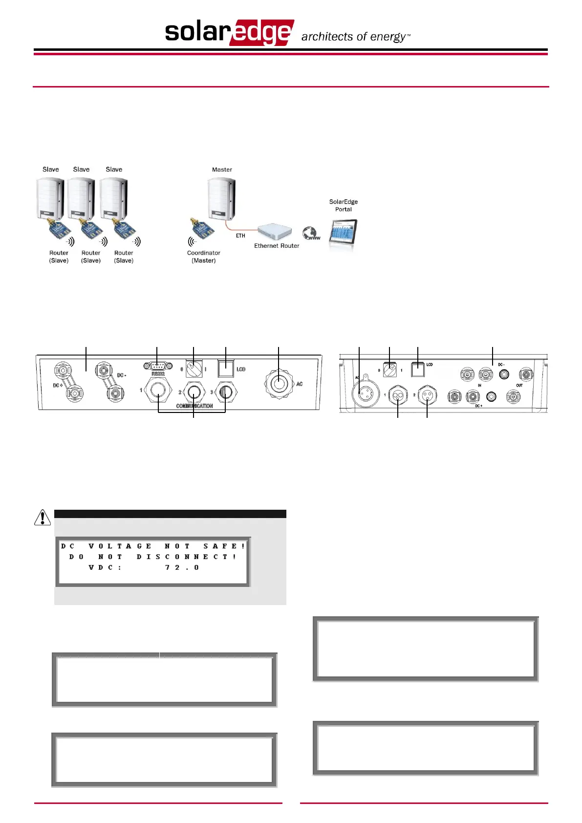
Figure 3 shows an inverter as an example. This illustration is can be applied to any
SolarEdge device connection.
This configuration enables you to wirelessly interconnect several SolarEdge
devices in a master/slave configuration (point to multipoint (P2MP)
configuration). In this configuration, the master device can optionally be
connected to the Internet (WWW) using an Ethernet router/switch.
Figure 3: Multiple Devices, ZigBee Bus, Ethernet Server Connection
The SolarEdge devices can be configured in
one of two ways:
Method A – Configuring the Devices
Using the LCD Button: When using
this option, there is no need to open the
device’s cover in order to set it up.
Method B – Configuring the Devices
Using the User Buttons: When using
this option, the device’s cover is
removed and the AC power is turned on
in order to set it up.
These configuration options are described in
detail below. You can choose either one of
them.
► Method A – Configuring SolarEdge Devices Using the LCD Button
The connector panel on the inverter and Safety and Monitoring Interface appears as shown below:
Figure 4: Inverter Connector Panel Figure 5: Safety and Monitoring Interface Connector panel
Use the LCD button to toggle through the informative status screens. The LCD button can also be used for communication setup.
For the slave devices, select the following:
1 Verify that the device’s ON/OFF switch is OFF.
2 Press the LCD Light button once to turn ON the backlight.
WARNING!
If the SolarEdge device worked properly before this action, the
following message is displayed:
This message is displayed until the DC is below the safety voltage
threshold. The default safety voltage is 50 V.
3 Short press the LCD button to scroll through the
informative screens to show the ID status window and
check the CPU firmware version. The correct configuration
sequence depends on the CPU version.
4 Access the LCD button Setup mode. Press and hold down
the LCD button until the following message is displayed:
5 Release the button within three seconds.
A short press scrolls down to the next menu option and a
long press selects the item. You can use the Exit option in
these menus to move up one menu level.
6 Scroll down to the Communication submenu and select it.
For FW versions above 2.250, continue to step 13. For
earlier versions complete steps 6 through 12 below.
7 Select the Server submenu, scroll down to the Zigbee
option and select it. The device performs a reset
immediately after the selection is made.
Server Submenu:
8 Repeat steps 4 through 6 above to access the Setup mode.
9 Scroll down to the Bus submenu and select it.
Communication Submenu:
 Loading...