EasyManua.ls Logo

Sony HCD-SBT300W User Manual

Sony HCD-SBT300W
88 pages
To Next Page IconTo Next Page
To Previous Page IconTo Previous Page
Page #19 background imageLoading...
Page #19 background image
HCD-SBT100/SBT100B/SBT300W/SBT300WB
19
2-16. MAIN BOARD
2-17. POWER CORD (AC1)
4 screw
(BVTP3 u 8)
4 screw
(BVTP3 u 8)
3 radiation sheet
4 screw
(BVTP3 u 8)
7 MAIN board
MAIN board
ditch
4 five screws
(BVTP3 u 8)
1 two screws
(BVTP3 u 8)
2 heatsink
(AMP)
6 tape
(sub material)
tape
(sub material)
Top view –– Bottom view
Rear view
Tape VXE materiaO VettiQJ
MAIN board
ditch
tape
(sub material)
5 Remove the MAIN board block
in the direction of an arrow.
70 to 75 mm
3 power cord
(AC1)
2 cord bush
(2104)
power cord
claw
cord bush
(2104)
&RUGEXVKVHWWLQJ
1 power cord connector
(CN901)
Insert is shallow
Insert is straight
to the interior.
Insert is incline
connector
connector
connector
connector
NGOK NG
connector
connector
Note:
When you install the connector, please install them correctly.
There is a possibility that this machine damages when not
correctly installing it.
Note: When the complete MAIN board is replaced, refer to “CHECKING
METHOD OF NETWORK CONNECTION” on page 5.

Table of Contents

Question and Answer IconNeed help?

Do you have a question about the Sony HCD-SBT300W and is the answer not in the manual?

Sony HCD-SBT300W Specifications

General IconGeneral
BrandSony
ModelHCD-SBT300W
CategoryCar Receiver
LanguageEnglish

Summary

HCD-SBT100/SBT100B/SBT300W/SBT300WB Service Manual

Servicing Notes

Handling Optical Pick-up and Laser Diode

Precautions for handling sensitive optical components and laser diodes.

Operation Checks After Repair

Procedures for verifying unit functionality after service.

Capacitor Discharge and WiFi Module Replacement

Procedures for safe capacitor discharge and WiFi module replacement.

Disassembly Procedures

Main Board and Power Board Replacement

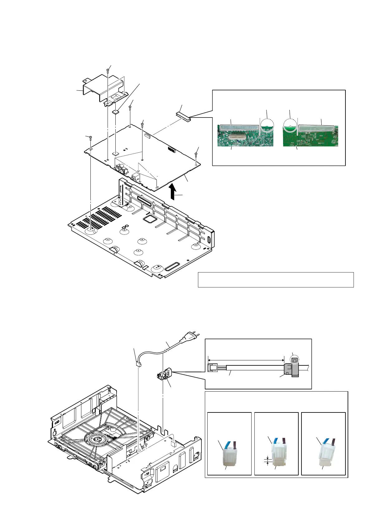
Steps for replacing the main and power supply boards.

Optical Pick-up Unit Replacement

Instructions for replacing the optical pick-up mechanism.

Test Modes and Checks

Functional Test Modes

Procedures for auto standby, common, and panel tests.

Diagrams and Schematics

Main Board Schematic Diagrams

Detailed circuit schematics for the main control board.

Peripheral Board Schematics

Schematics for USB, HP, Relay, NET, FL, and KEY/ILLUMI boards.

Power Board Schematic Diagram

Circuit diagram for the power supply section.

Waveforms and IC Block Diagrams

Visual representations of signals and functional blocks of ICs.

Electrical Parts List

Related product manuals