EasyManua.ls Logo

Sony HCD-SBT300WB User Manual

Sony HCD-SBT300WB
88 pages
To Next Page IconTo Next Page
To Previous Page IconTo Previous Page
Page #9 background imageLoading...
Page #9 background image
HCD-SBT100/SBT100B/SBT300W/SBT300WB
9
Note: Follow the disassembly procedure in the numerical order given.
2-2. CASE BLOCK
2-3. PLATE (CD) ORNAMENT BLOCK
4 case block
1 screw (BVTP S3 u 6)
1 screw
(BVTP S3 u 6)
1 three screws
(BVTP S3 u 6)
3 Remove the case block in the
direction of an arrow.
2
2
3 two claws
4 plate (CD) ornament
block
1 Insert the clip etc. in the hole
of the chassis, and push the
lever in the direction of the
arrow.
2 Draw out the tray.
tray
CD mechanism deck
HP board
Insert the clip etc. processed to the
length of 8 cm or more in the hole
on the side of the chassis and push.
8 cm or more
Top view
Note:
Push after it inserts it
in these three holes well.
Side view
hole

Table of Contents

Question and Answer IconNeed help?

Do you have a question about the Sony HCD-SBT300WB and is the answer not in the manual?

Sony HCD-SBT300WB Specifications

General IconGeneral
BrandSony
ModelHCD-SBT300WB
CategoryCar Receiver
LanguageEnglish

Summary

Specifications Overview

Amplifier, Tuner, Wireless, General, Optical Specs

Details on amplifier, tuner, wireless connectivity, general specs, optical playback, and media support.

Safety and Warnings

Safety Check-out and Leakage Tests

Procedures for ensuring safety after repair, including leakage tests and checks.

Component Handling and Critical Component Notes

Precautions for handling chip components, optical parts, and identifying safety-critical parts.

Servicing Notes

General Handling and Solder Usage Notes

Essential notes for technicians on unit handling, unleaded solder, and optical pick-up precautions.

Component Replacement Guidance

Specific notes on replacing boards and ICs, including handling of critical components.

Disassembly Procedures

Disassembly Flowchart and Major Block Removal

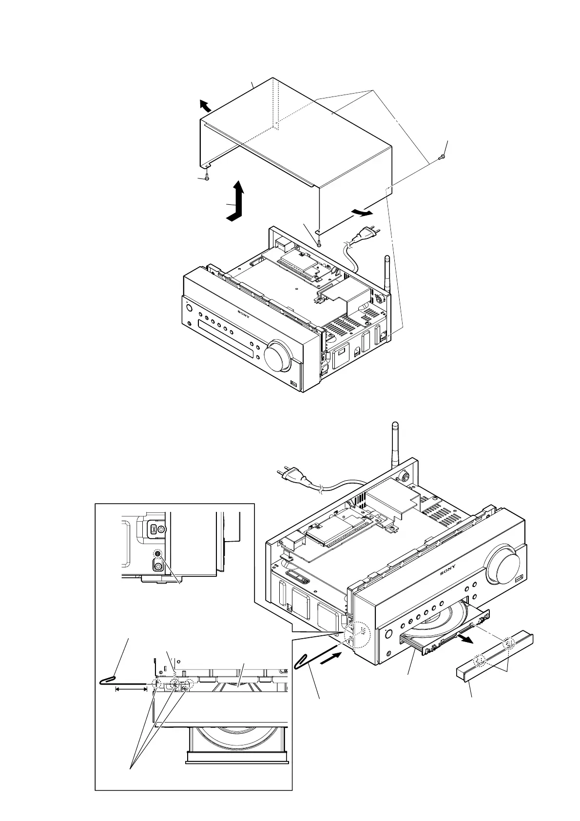
A visual flowchart and steps for disassembling the main unit sections.

Specific Component Disassembly

Detailed steps for removing case, CD mechanism, panels, and boards.

Test Modes and Electrical Checks

Test Mode Operations

Procedures for cold reset, auto standby, common, and panel tests.

Electrical Verification Procedures

Methods for checking tuner signal reception and CD section RF signals.

Technical Diagrams and Illustrations

Block Diagrams (CD, Audio, Panel/Power)

Block diagrams illustrating signal paths and circuitry.

Schematic Diagrams (Main Board)

Detailed schematic diagrams covering all seven sections of the MAIN board.

Printed Wiring Boards (PWBs)

Layouts for Main, USB, HP, Relay, NET, FL, KEY, ILLUMI, and Power boards.

Waveforms and IC Block Diagrams

Diagrams showing signal waveforms and IC internal logic.

IC Pin Function Descriptions

Detailed pinout information for major ICs on the MAIN board.

Exploded Views

Exploded Views of Major Assemblies

Illustrated breakdown of unit assemblies for parts identification.

Electrical Parts List

Component Parts Lists by Board

Comprehensive list of electrical components by board type, including resistors, capacitors, ICs, etc.

Related product manuals