23
Connections and Settings
Sub-Camera System
Use an HDC-P1, etc. as the sub camera, which can be
controlled via the AUX REMOTE connector of the HDCU2000.
Note
AES/EBU signal cannot be used between the camera and
camera control unit.
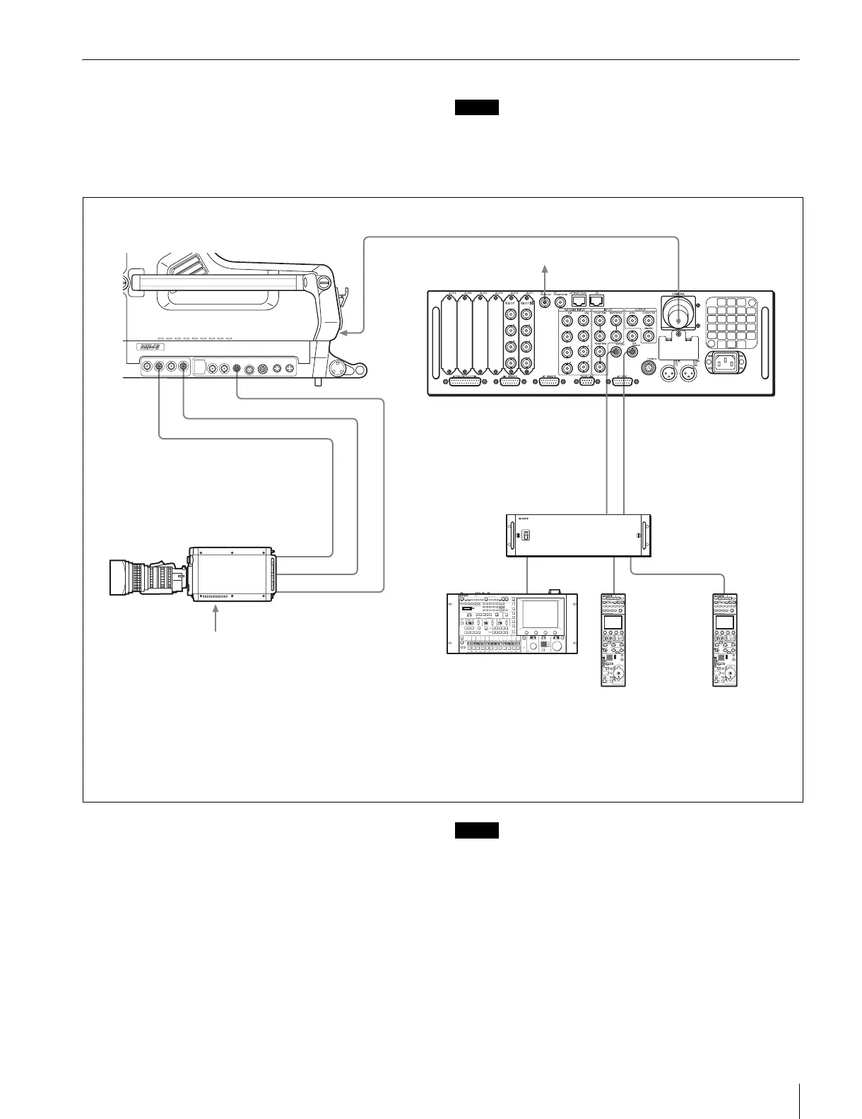
Connection example
Settings
Main camera
MAINTENANCE menu, <TEST OUT> page:
Set OUTPUT to HD-SYNC or SD-SYNC.
<SDI OUT> page: Set SDI-2 OUT/IN to HD TRUNK/RET
IN.
Sub camera
Enable the genlock function.
(When NETWORK TRUNK in <PROMPT/TRUNK 2> of the
CCU CONFIGURATION menu is set to the NETWORK +
VIDEO mode, you do not need to enable the genlock signal
connection and genlock function.)
Note
To use the tally function of the sub camera, supply the tally
signal directly to the sub camera.
Camera control unit
Format: Set it to a Single Link format.
CCU CONFIGURATION menu, <PROMPT/TRUNK 1> page:
Set AUX REMOTE to ENABLE.
SDI 1 SDI 2
TEST OUTSDI MONI
OUTPUT PROMPTER REMOTE
12
CRANE TRACKER RET
CONTROL
NETWORK
TRUNK
DC
OUT
RCP/CNU AUX REMOTE
CAMERA
REMOTE
SDI-1/SDI-2
REMOTESDI 2 TEST
OUT
CCU
GENLOCK
HD TRUNK OUT
HDCU2000
DC power
1)
Main camera (HDC2000)
Sub camera (HDC-P1, etc.)
Optical fiber cable (High Bit Rate)
(HD-SYNC or SD-SYNC)
CCA cable
Sub camera signal output
2)
BNC cable (HD-SDI)
CNU-700
Camera Network Unit
RCP-1000-series
Remote Control Panel
(for main camera)
RCP-1000-series
Remote Control Panel
(for sub camera)
1) A dedicated power source is required for the sub camera.
No power is supplied from the camera control unit.
2) Adjust the phase of the sub camera signal output on the
sub camera.
If NETWORK TRUNK in <PROMPT/TRUNK 2> of the
CCU CONFIGURATION menu is set to the NETWORK +
VIDEO mode, the phase of the sub camera signal output
is locked.
CCA cable
CCA cable
MSU-1000/1500
Master Setup Unit
BNC cable

 Loading...


