 Loading...
Do you have a question about the Sony ICF-SW35 and is the answer not in the manual?
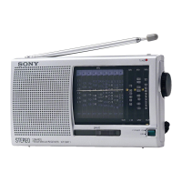
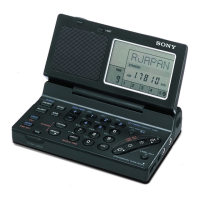
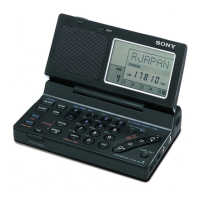
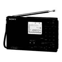
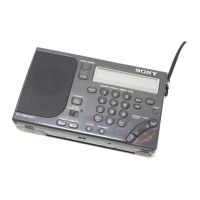
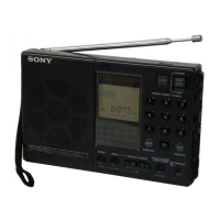
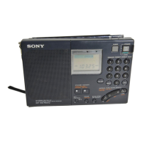
| Radio type | Portable |
|---|---|
| Tuner type | Digital |
| FM band range | 87.5 - 108 MHz |
| Driver unit | 66 mm |
| Number of built-in speakers | - |
| Display type | LED |
| Headphone outputs | 1 |
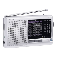
| Product color | Silver |
| Battery type | AA |
| Battery life (max) | 33 h |
| Number of batteries supported | 3 |
| Dimensions (WxDxH) | 168 x 35 x 106 mm |
| Weight | 405 g |
|---|
Physical size of the radio unit.
Weight of the radio unit with batteries.
Items included with the radio.
Voltage and current needs for operation.
Estimated operational hours with different battery types.
Instructions for turning on and using the radio.
Details on tuning increment adjustment.
How to enjoy stereo sound with headphones.
Adjusting tone for news or music.
Changing the MW tuning step for different regions.
How to automatically scan and find stations.
Adjusting reception sensitivity to control scan pauses.
Storing, tuning, and deleting favorite stations.
Automatically scanning stations within a preset page.
Optimizing reception via antenna and external options.
Programming auto-on times and alarm features.
Setting the radio to turn off automatically after a specified duration.
Using the hold function to lock buttons and activating the display backlight.
Procedure for removing the rear cabinet cover.
Steps to access and remove the main circuit board.
Procedure for removing the micon circuit board.
Calibration procedures for the FM tuning circuit.
Calibration for shortwave, medium, and longwave bands.
Verifying reception and tuning alignment across bands.
Calibrating the Voltage Controlled Oscillator for FM reception.
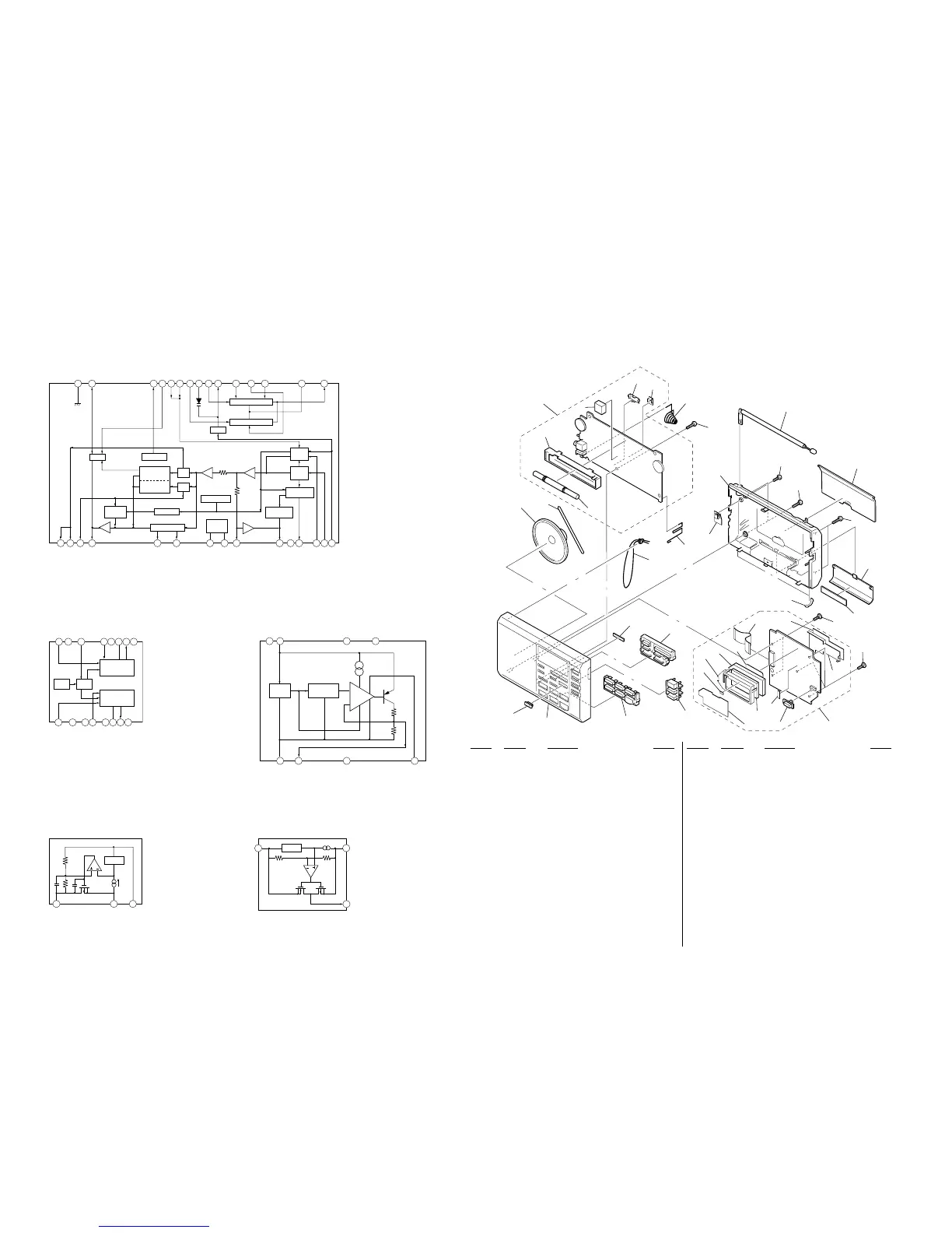
Detailed pin assignments for integrated circuits.
Overview of the radio's internal functional blocks.
Visual guide to component placement on the main circuit board.
Detailed electrical wiring diagram for the main board.
Visual guide to component placement on the micon circuit board.
Detailed electrical wiring diagram for the micon board.
Diagram showing the breakdown of the radio's cabinet parts.