NEX-FS100C/FS100CK/FS100E/FS100EK/FS100J/FS100JK/FS100N/FS100NK/FS100P/FS100PK/FS100U/FS100UK
2-11
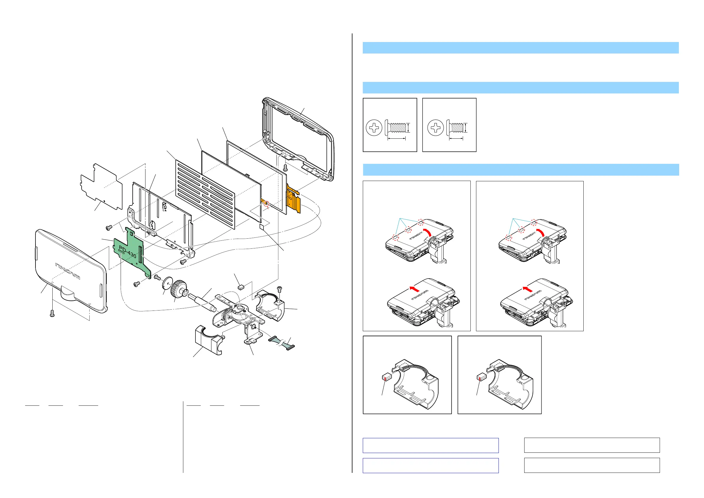
2-1-9. LCD SECTION
Note
Screw
Note 3: Refer to "Assembly-6: Apply grease on the LCD Lock
Bolt.".
Note 3:
“Assembly-6: Apply grease on the LCD Lock Bolt.”
を参照してください。
Note 4: Cut SHEET
, LIGHT INTERCEPTION (3-089-986-01)
into the desired length and use it.
Note 4:
SHEET, LIGHT INTERCEPTION (3-089-986-01)は
指定のサイズに切って使用すること。
Note 1:
P Cabinet (C) Assyの爪の無い側を矢印方向に
持ち上げる。
P Cabinet (C) Assyの爪を折らないために、
以下の手順でP Cabinet (C) Assyを取り外し
てください。
1
P Cabinet (C) Assyを矢印方向にスライドさせて
P Cabinet (C) Assyを取り外す。
2
Claws
401 4-269-207-01 CABINET (C), P (Note 1)
402 A-1826-052-A PD-430 BOARD, COMPLETE
403 4-269-204-01 SHEET (PD)
404 4-269-203-01 FRAME, LCD
405 4-283-280-11 CUSHION (91000), LCD
406 4-269-202-01 CABINET (M), P
407 1-471-504-11 MAGNET (ND5X3.5X2.4-B) (Note 2)
408 4-269-197-01 CAP, LCD KNOB
409 4-269-196-01 KNOB, LCD LOCK (Note 3)
410 4-269-195-01 BOLT, LCD LOCK (Note 3)
Ref. No. Part No. DescriptionRef. No. Part No. Description
411 4-269-206-01 CABINET (REAR), HINGE
412 1-967-783-11 HARNESS (COAXIAL CABLE)
413 X-2580-324-1 HINGE ASSY, PANEL
414 4-269-205-01 CABINET (FRONT), HINGE
415 3-089-986-01 SHEET (L), LIGHT INTERCEPTION (Note 4)
LCD901 1-811-403-11 LCD WITH TOUCH PANEL
LED901 1-487-270-11 BLOCK, LIGHT GUIDE PLATE (3.5)
#49 2-630-005-31 SCREW (M2), NEW TRUSTER, P2
#50 2-891-494-11 SCREW (M2), NEW TRUSTER, P2
#50
#49
#49
#49
#50
#50
#49
LCD901
LED901
401
(Note 1)
403
404
405
406
407
(Note 2)
409
408
410
(Note 3)
414
413
411
412
402
415
(Size: 5.0mm X 5.0mm)
(Note 4)
#49: M2.0 X 4.0
(Black)
2-630-005-31
4.0
2.0
#50: M2.0 X 3.0
(Red)
2-891-494-11
3.0
2.0
Put the marking side together
on the position of figure when
you install the magnet.
Marking
Note 2:
マグネットを取付ける際は,
マ−キング面を図の位置に
あわせてください。
マーキング
Note 2:
Note 1:
1
2
Claws
Install the P cabinet (C) assembly in the
following procedure to prevent the claw of P
cabinet (C) assembly from breaking.
Lift up the opposite side of the claw of P cabinet
(C) assembly in the arrow direction.
Remove the P cabinet (C) assembly, sliding it in
the arrow direction.
1. The meaning of the sign in left figure is as follows. Be careful when it removes.
◇ : Solder
DISASSEMBLY
Ver. 1.1 2012.05
 Loading...