HT-CT290/CT291
9
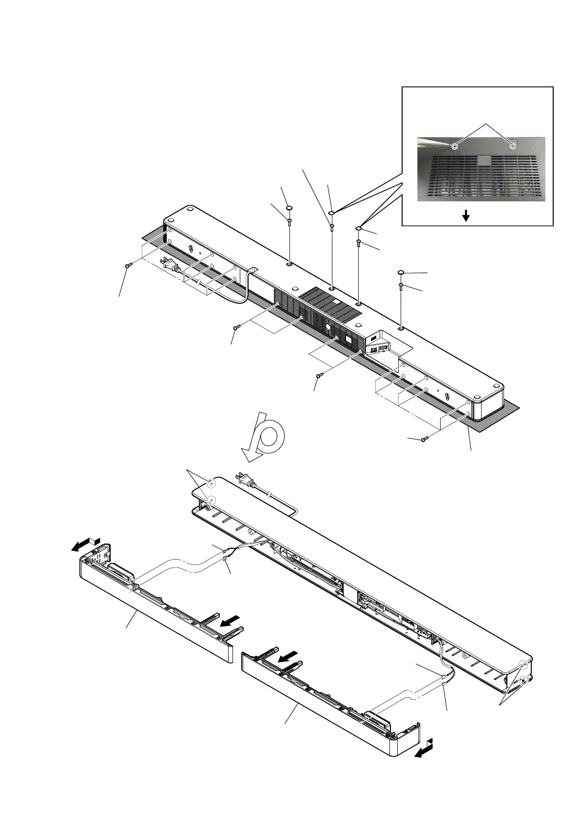
Note: Follow the disassembly procedure in the numerical order given.
2-2. LEFT, RIGHT PANEL (CG-BAR)
– Bottom view –
Note:
Please spread a sheet under the unit
so that do not damage the top panel.
5 six screws
(TPP + 3 u 10 (HR) - 3W ZN)
5 six screws
(TPP + 3 u 10 (HR) - 3W ZN)
qa two claws
6 two claws
7 Remove panel, left (CG-BAR)
gently to prevent grille, side
(CG-BAR) from bend.
qs Remove panel, right (CG-BAR)
gently to prevent grille, side
(CG-BAR) from bend.
8
qd
4 one screw
(TPP + 3 u 10
(HR) - 3W ZN)
4 one screw
(TPP + 3 u 10
(HR) - 3W ZN)
4 one screw
(TPP + 3 u 10 (HR) - 3W ZN)
4 one screw
(TPP + 3 u 10 (HR) - 3W ZN)
1 foot (CG-BAR)
3 cover, screw
(CG-BAR)
3 cover, screw (CG-BAR)
2 Insert the tweezer into the service hole
and raise the cover, screw.
1 foot (CG-BAR)
5 two screws
(TPP + 3 u 10
(HR) - 3W ZN)
5 two screws
(TPP + 3 u 10
(HR) - 3W ZN)
9 terminal
(wide side)
0 panel, left
(CG-BAR)
qg panel, right
(CG-BAR)
9 terminal
(narrow)
qf terminal
(wide side)
qf terminal
(narrow)
service holes
rear side