 Loading...
Do you have a question about the Sony STR-DE835 and is the answer not in the manual?
| Preset Stations | 30 |
|---|---|
| Power Output | 100 W per channel (8 ohms) |
| Tuning range | FM, AM |
| Input Sensitivity | 200 mV (line) |
| Speaker load impedance | 8 ohms |
| Digital inputs | optical, coaxial |
| Video Connections | Composite video in/out |
Detailed power output and total harmonic distortion figures for various models and configurations.
Technical specifications including inputs, outputs, tuner details, and power requirements.
Lists different model numbers and their corresponding parts identification.
Procedure for checking AC leakage from exposed metal parts to ground.
Critical components for safe operation identified by mark ▲.
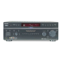
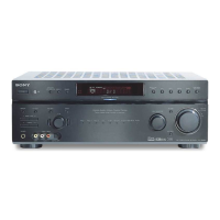
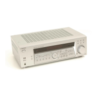
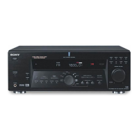
Identifies various controls and connectors on the front panel of the unit.
Important notes regarding servicing procedures and safety precautions.
Tests the functionality of the Digital Signal Processor (DSP) by outputting test data.
Resets all preset contents to the default factory settings.
Clears all preset contents, used before returning the product to the client.
Clears preset sound field settings before returning the product to the client.
High-level block diagram illustrating the main signal paths and components.
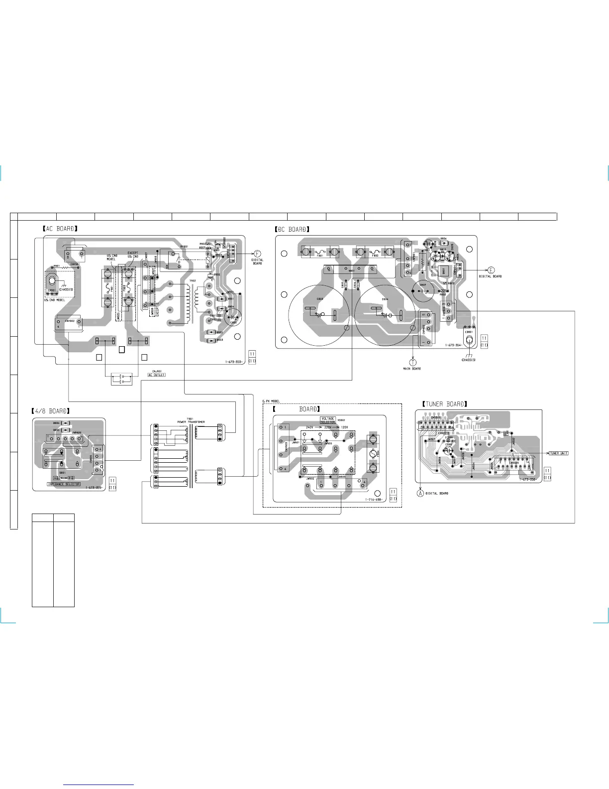
Diagrams showing the physical placement of various circuit boards within the unit.
Detailed schematic for the digital section, part 1 of 3.
Printed wiring board layout for the digital section, part 1 of 2.
Schematic diagram for the rear amplifier section.
Printed wiring board layout for the main processing section.
Pin function details for the CXD2712R Audio DSP IC.
Block diagrams illustrating the internal structure of key IC components.
Exploded view of the front panel assembly with part numbers.
Exploded view of the chassis assembly with part numbers.
Lists capacitors, resistors, semiconductors, and other components with part numbers.
List of included accessories and packing materials with part numbers.
Contains corrections and additions to the main service manual.
Records changes and updates made to the service manual over different versions.