Hardware layout and configuration UM1724
22/68 UM1724 Rev 14
1. Connect the jumper between pin 2 and pin 3 of JP5
2. Check that JP1 is removed
3. Connect the external power source to VIN or E5V
4. Power on the external power supply 7 V< VIN < 12 V to VIN, or 5 V for E5V
5. Check that LD3 is turned ON
6. Connect the PC to USB connector CN1
If this order is not respected, the board may be supplied by VBUS first then by VIN or E5V,
and the following risks may be encountered:
1. If more than 300 mA current is needed by the board, the PC may be damaged or the
current supply can be limited by the PC. As a consequence, the board is not powered
correctly.
2. 300 mA is requested at enumeration (since JP1 must be OFF) so there is a risk that the
request is rejected and the enumeration does not succeed if the PC cannot provide
such current. Consequently, the board is not power supplied (LED LD3 remains OFF).
6.3.3 External power supply input: +3.3V
It can be of interest to use the +3.3V (CN6 pin 4 or CN7 pin 12 and pin 16) directly as power
input for instance in case the 3.3V is provided by an extension board. When the STM32
Nucleo board is power supplied by +3.3V, the ST-LINK is not powered, thus the
programming and debug features are unavailable. The +3.3V external power source is
summarized in
Table 9.
Two different configurations are possible when using +3.3V to power the board:
• ST-LINK is removed (PCB cut) or
• SB2 (3.3V regulator) and SB12 (NRST) are OFF.
6.3.4 External power supply output
When powered by USB, VIN, or E5V, the +5V (CN6 pin 5 or CN7 pin 18) can be used as an
output power supply for an ARDUINO
®
shield or an extension board. In this case, the
maximum current of the power source specified in
Table 7 must be respected.
The +3.3V (CN6 pin 4 or CN7 pin 12 and 16) can be used also as power supply output. The
current is limited by the maximum current capability of the regulator U4 (500
mA max).
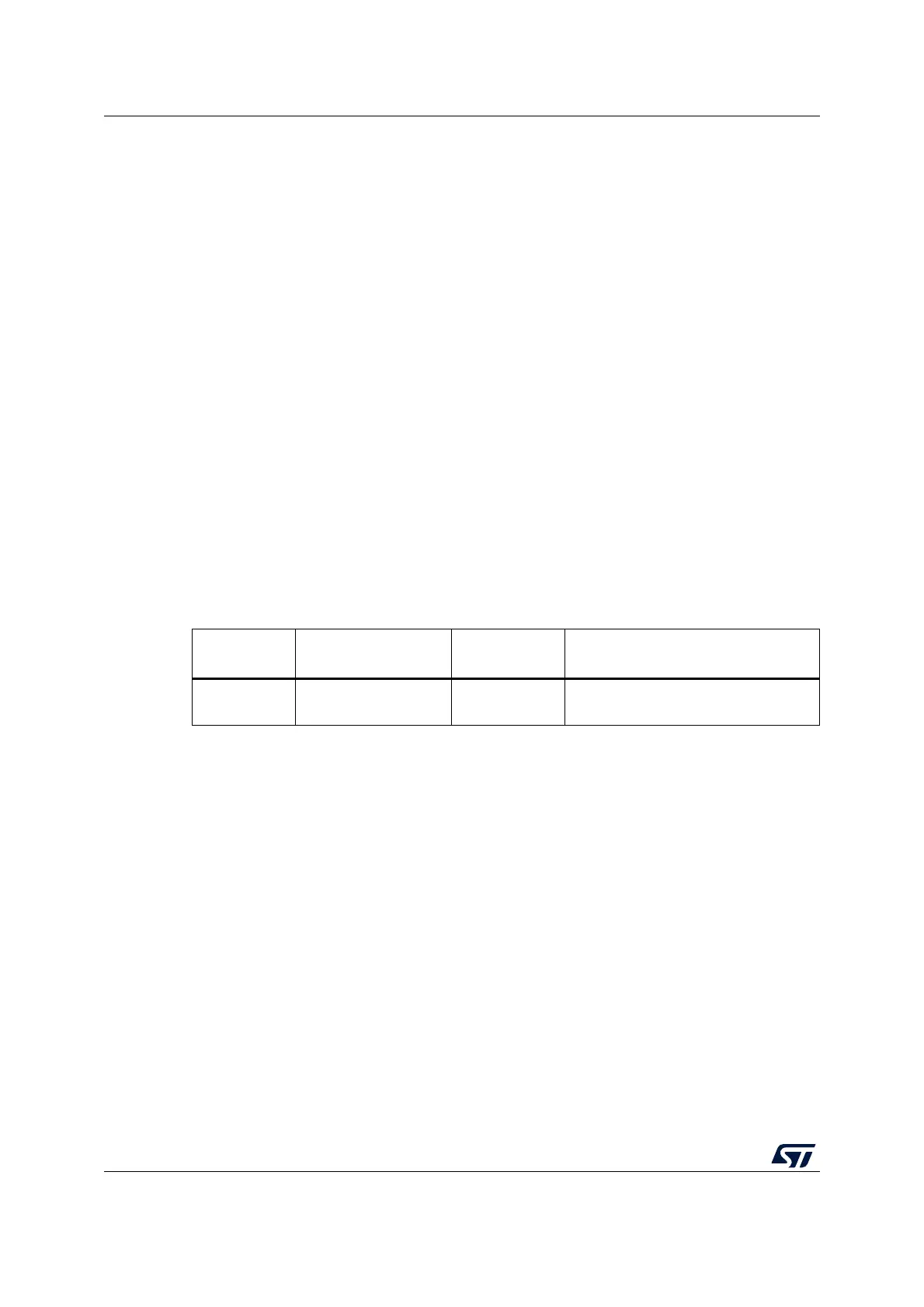
Table 9. +3.3 V external power source
Input power
name
Connectors pins Voltage range Limitation
+3.3V
CN6 pin 4
CN7 pin 12 and pin 16
3 V to 3.6 V
Used when ST-LINK part of PCB is cut
or SB2 and SB12 OFF
 Loading...