Connectors UM2198
34/69 DocID030511 Rev 1
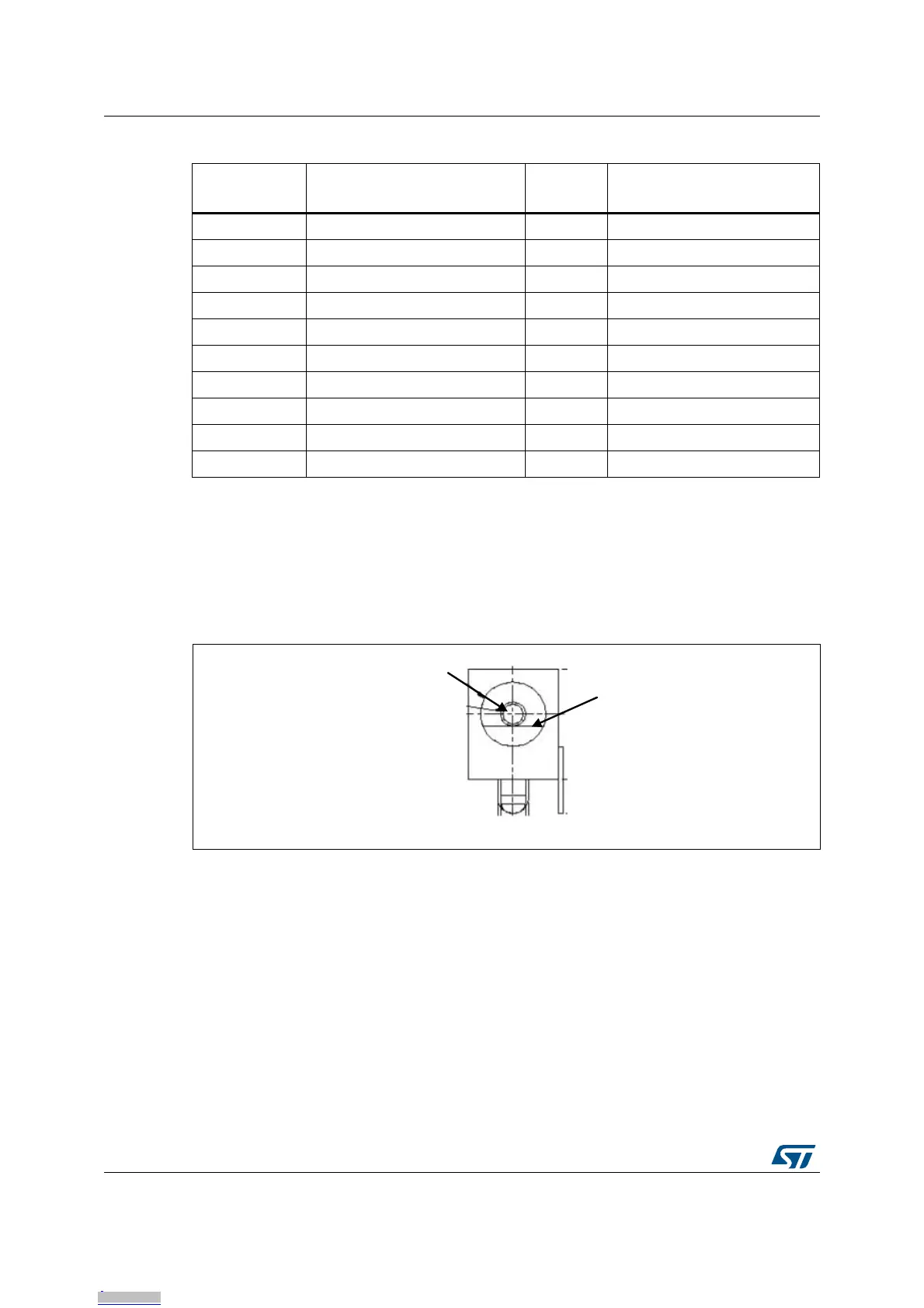
9.9 Power connector CN10
STM32H743I-EVAL Evaluation board can be powered from a DC 5 V power supply through
the external power supply jack (CN10) shown in Figure 14. The central pin of CN10 must be
positive.
Figure 14. Power supply connector CN10 (front view)
9.10 Memory connector CN11 and CN12
Two 40-pin male headers CN11 and CN12 are used to connect with memory
daughterboard.
All GPIOs are connected on the extension connectors CN6 and CN7, but the GPIOs which
are used for FMC memory signals, are connected on CN11 and CN12.
The space between these two connectors is defined as a standard that allows to develop
common daughterboard. The standard width between CN11 pin1 and CN12 pin1 is 1914
mils (48.62 mm). For details on signals assignment refer to Table 25 and Table 26.
Table 24. JTAG/SWD debugging connector CN9
Pin number Description
Pin
number
Description
1 +3.3V 2 +3.3V
3 TRST(PB4) 4 GND
5 TDI(PA15) 6 GND
7 TMS/SWDIO(PA13) 8 GND
9 TCK/SWCLK(PA14) 10 GND
11 RTCK 12 GND
13 TDO/SWO(PB3) 14 GND
15 RESET# 16 GND
17 DBGRQ(PJ7) 18 GND
19 DBGACK(PJ12) 20 GND
Downloaded from Arrow.com.Downloaded from Arrow.com.Downloaded from Arrow.com.Downloaded from Arrow.com.Downloaded from Arrow.com.Downloaded from Arrow.com.Downloaded from Arrow.com.Downloaded from Arrow.com.Downloaded from Arrow.com.Downloaded from Arrow.com.Downloaded from Arrow.com.Downloaded from Arrow.com.Downloaded from Arrow.com.Downloaded from Arrow.com.Downloaded from Arrow.com.Downloaded from Arrow.com.Downloaded from Arrow.com.Downloaded from Arrow.com.Downloaded from Arrow.com.Downloaded from Arrow.com.Downloaded from Arrow.com.Downloaded from Arrow.com.Downloaded from Arrow.com.Downloaded from Arrow.com.Downloaded from Arrow.com.Downloaded from Arrow.com.Downloaded from Arrow.com.Downloaded from Arrow.com.Downloaded from Arrow.com.Downloaded from Arrow.com.Downloaded from Arrow.com.Downloaded from Arrow.com.Downloaded from Arrow.com.Downloaded from Arrow.com.

 Loading...


