6.7 STEERING WHEEL (12:D)
The height of the steering wheel is fully adjustable.
Unscrew the adjustment knob (12:E) on the stee-
ring column and raise or lower the steering wheel
accordingly. Tighten.
Do not adjust the steering wheel when
the machine is running.
Never turn the steering wheel when the
machine is stationary with a lowered
accessory. There is a risk of abnormal
loads on the servo and steering mecha-
nisms.
6.8 THROTTLE CONTROL (ACCELERATOR)
(13:A)
Control for regulating engine running speed.
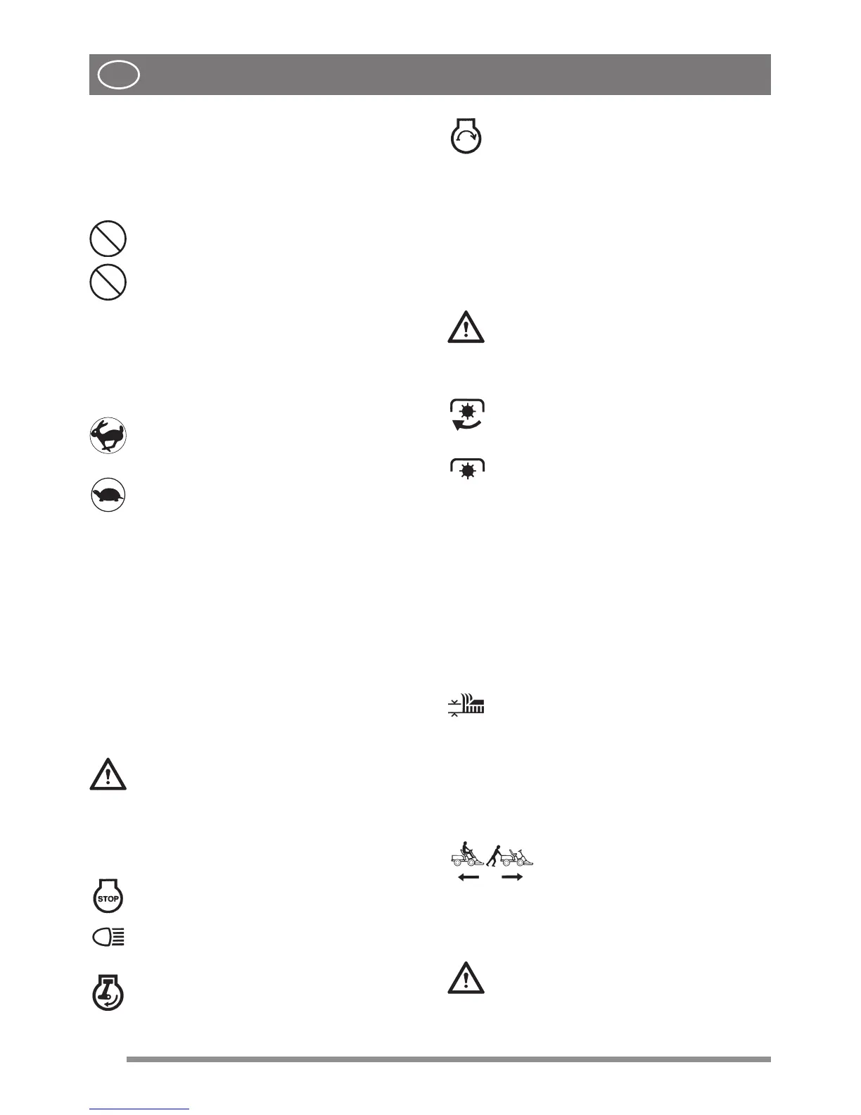
1. Full throttle – should always be used
when the machine is in use.
2. Idling.
6.9 HEADLAMPS CONTROL (13:B, 14:B)
Pull-out control for turning the headlamps on and
o.
Start-up:
pull the knob (13:B, 14:B) up, pos. B1.
Push the knob (13:B, 14:B) down, pos. B2.
6.10 IGNITION BLOCK (13:C, 14:C)
The ignition block is used for starting and stopping
the engine.
Do not leave the ignition key in position
2 or 3 when you leave the driving seat.
the engine through the carburettor) and
-
ged.
The four ignition key positions:
1. Stop position – the engine is short-cir-
cuited. The key can be removed.
2. Function not present, see (13:B, 14:B)
3. Operating position.
4. Start position – the electric starter mo-
tor is activated when the key is turned to this
position. Once the engine has started, let
go of the key which will return to operating
position 3.
6.11 POWER TAKE-OFF (13:D, 14:D)
Switch for engaging and disengaging the elec-
tromagnetic PTO used to activate front-mounted
accessories.
The PTO must never be engaged when
the front accessory lift is in the tran-
sport position. This will destroy the belt
drive.
The switch has two positions:
1. Engaged - to engage the PTO press the
front part of the switch. If the light is on it
means the PTO is engaged.
2. Disengaged - to disengage the PTO
press the rear part of the switch. If the light
is o it means the PTO is disengaged.
6.12 HOUR METER (15:B)
Indicates the number of service hours completed.
Only works when the engine is running.
6.13 CUTTING HEIGHT ADJUSTMENT [4WD]
(13:E, 14:E)
The machine is equipped with a control for using
the cutting device with electrical cutting height
adjustment.
The switch allows the user to continuously
adjust the cutting height.
The cutting means are connected to the contact
(14:A).
6.14 TRANSMISSION RELEASE LEVER (16,
17)
A lever for disengaging the variable transmission.
Model [2WD]
Is equipped with a lever, connected
to the rear axle. See (16:A).
Model [4WD]
Is equipped with two levers (17:A, 17:B)) con-
nected to the rear and front axle respectively.
The engagement/release lever must
never be between the outer and inner
positions. This overheats and damages
the transmission.
 Loading...