• When the machine is withdrawn from service,
do not dump it in the environment, but take it to
a waste disposal facility in accordance with the
local regulations in force.
3.7 MAINTENANCE AND ASSISTANCE
Before proceeding to hook-up/unhook the cutting-
means assembly to/from the machine, perform
washing procedures or maintenance in general:
Activate the parking brake (please refer
-
-
nect the (negative) lead from the bat-
tery.
Remove the key from the ignition. (Plea-
Wear protective gloves
• Tighten all nuts and screws to ensure safe
accessory operations.
• Regularly check that the cutting means screws
are securely tightened.
• For the sake of safety, replace worn or damaged
parts.
• Replace any damaged warning and instruction
stickers.
4 CONTROLS
4.1 CUTTING HEIGHT ADJUSTMENT
The cutting height can be adjusted between 25 -
90 mm.
The cutting height is fully adjustable with minute
precision by acting on the relative switch (if pre-
sent) on the main machine.
The indicator (1:F) shows the height adjustment.
inserted in the socket (9:A) on the ma-
chine.
The cutting height can be adjusted to a number of
xed positions using the lever (3:A).
The pointer (3:B) indicates the height adjustment.
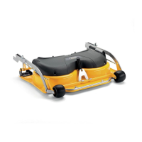
4.2 FORWARD TILT
The rear section of the cutting deck assy can be
raised 12 mm by moving the two cotter pins or
pegs (4:A) down one hole on the supports (4B).
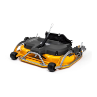
5 HOOKING THE CUTTING DECK
UP TO THE MACHINE
The cutting deck assy must be hooked up to the
main machine by means of the mounts attached to
the front wheels and a chain which is connected to
the accessory lift hook.
The mounts are attached to the arms (1:A).
5.1
The cutting deck assy must be hooked up to the
“accessories lift lever” (8:A) on the main machine
by means of a chain and clip-on hooks.
One clip-on hook (8:B) is for the operating position
and can be moved between the chain links to
adjust the lifting force.
The other clip-on hook (8:C) is for the washing
position.
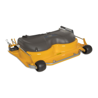
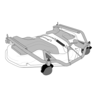
5.2 HOOK UP TO THE MOUNTS ATTACHED
TO THE WHEELS
5.2.1
1. Bring the cutting-means assembly up to the
machine, insert the electric cable plug in the
socket (9:A) and set the cutting height to ma-
ximum. See 4.1.
2. Disconnect the plug from the socket.
5.2.2
Example of xed mounts, see (5:C and 6:A).
Follow the indications provided in hea-
ding 3.7.
1. Place the cutting device assy in front of the
machine.
2. The cutting-means assembly mounts are in-
stalled on the machine axles as follows:
 Loading...