53
ENGLISH
GB
1 GENERAL
This symbol indicates CAUTION. Seri-
ous personal injury and/or damage to
property may result if the instructions
are not followed carefully.
You must read these instructions for use
and the accompanying pamphlet
“SAFETY INSTRUCTIONS” careful-
ly, before starting up the machine.
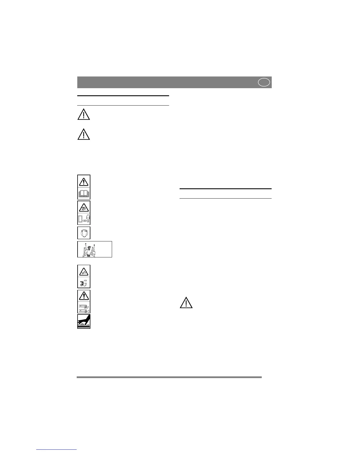
1.1 SYMBOLS
The following symbols appear on the machine.
They are there to remind you of the care and atten-
tion required during use and maintenance.
This is what the symbols mean:
Warning!
Read the instruction manual and the safety
manual before using the machine.
Warning!
Watch out for discarded objects. Keep on-
lookers away.
Warning!
Always wear hearing protectors.
Warning!
The machine must not be driv-
en in any direction on slopes
with a gradient greater than
10º.
Warning!
Before starting repair work, remove the
spark plug cable from the spark plug.
Warning!
Do not insert your hands or feet under the
cutting deck cover when the machine is in
operation.
Warning!
Risk of burn injuries. Do not touch the si-
lencer.
1.2 References
1.2.1 Figures
The figures in these instructions for use are num-
bered 1, 2, 3, etc.
Components shown in the figures are marked A, B,
C, etc.
A reference to component C in figure 2 is written
as follows:
“See fig. 2:C.” or simply “(2:C)”
1.2.2 Headings
The headings in these instructions for use are num-
bered in accordance with the following example:
“1.3.1 General safety checks” is a subheading to
“1.3 Safety checks” and is included under this
heading.
When referring to headings, only the number of the
heading is normally specified. E.g.“See 1.3.1”.
2 ASSEMBLY
2.1 Steering wheel
See fig. 2. Install the steering wheel as follows:
1. Install the steering column jacket on the steer-
ing column using a drift or similar so that the
holes in the steering column jacket and steering
column align with each other.
2. Tap in the supplied tension pin from the other
side using a hammer.
2.2 Backrest (3:N)
Install the backrest as follows:
1. Fold the seat up towards the steering wheel.
2. Remove the screws (3:O) from the seat.
3. Install the backrest with the screws (3:O) with-
out tightening.
4. Set the backrest to the desired position. See also
3.4.8.
5. Tighten the screws. Tightening torque: 20-24
Nm.
If the screws are tightened more than 24
Nm, the seat will be damaged.
2.3 Seat (1:A)
Adjust the seat backwards/forwards to a comforta-
ble driving position.
See 3.4.7.
2.4 Battery
See fig. 4. Fold the seat up and install the battery
leads.
See warnings and instructions in 6.11.
2.5 Tyre pressure
Check the air pressure in the tyres. See 6.5.
 Loading...