The machine is supplied with
some of the components disassembled and the
fuel tank empty.
Always wear strong work
gloves to handle the cutting devices. Mount
the components very carefully so as not to
impair the safety and efficiency of the ma-
chine. If in doubt, contact your dealer.
1. COMPLETING THE MACHINE
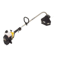
1a. “MONO” models (Fig. 1)
The purpose of the spacer
(1) is to ensure a minimum distance between
the rear handgrip and the front one, for safety
reasons. This spacer must always be fitted
and must not be modified in any way.
– In front of the spacer (1), position the upper part
(2) with the front grip’s guard.
– Fasten the lower cap (4) to the upper part (2) with
screws (5).
– Before tightening the screws (4), align the hand-
grip correctly with respect to the drive tube.
– Fully tighten the screws (4).
1b. “DUPLEX” models (Fig. 2)
– Loosen the screws (5) and remove the cap (4)
from the support (2).
– Put the handlebar (1) into the seating in the sup-
port (2), located on the drive tube (3), making
sure that the controls are on the right.
– Fit the cap (4), fully tightening the screws (5).
– Fasten the casing (6) of the controls to its cable
fastener (7).
2. MOUNTING THE ROD
(Models with separate rod – Fig. 3)
– Pull out the stop pin (5) and push the lower part
of the rod (4) right down until the stop pin (5) slots
into the hole (6) in the rod. This is easier to do if
you rotate the bottom of the rod (4) slightly in
WARNING!
WARNING!
IMPORTANT
both directions. The pin (5) is in place when it is
completely lodged in the hole.
– Lastly, tighten the knob (7) securely.
3. FITTING THE GUARDS
Each cutting device is
provided with a specific guard. Never use
guards other than those indicated for each
cutting device.
• 3 point blade (Fig. 4)
Wear protective gloves
and fit the blade guard.
– Remove the blade (if fitted) as described in para-
graph 4.
– The guard (1) is fixed to the angle transmission
(2) by four screws (3).
• Cutting line head (Fig. 5)
When using the cutting
line head the additional guard, with line cutting
knife, must always be fitted.
– Remove the blade (if fitted) as described in para-
graph 4.
– The guard (1) is fixed to the angle transmission
(2) by four screws (3).
– Assemble the additional guard (4) fastening it
into place on the guard (1).
4. REMOVING AND REFITTING
THE CUTTING DEVICES
Use only original cutting
devices or ones homologated by the Manu-
facturer.
• 3 point blade (Fig. 6)
Wear protective gloves
and fit the blade guard.
WARNING!
WARNING!
WARNING!
WARNING!
WARNING!
6 MACHINE ASSEMBLY
EN
4. MACHINE ASSEMBLY
 Loading...