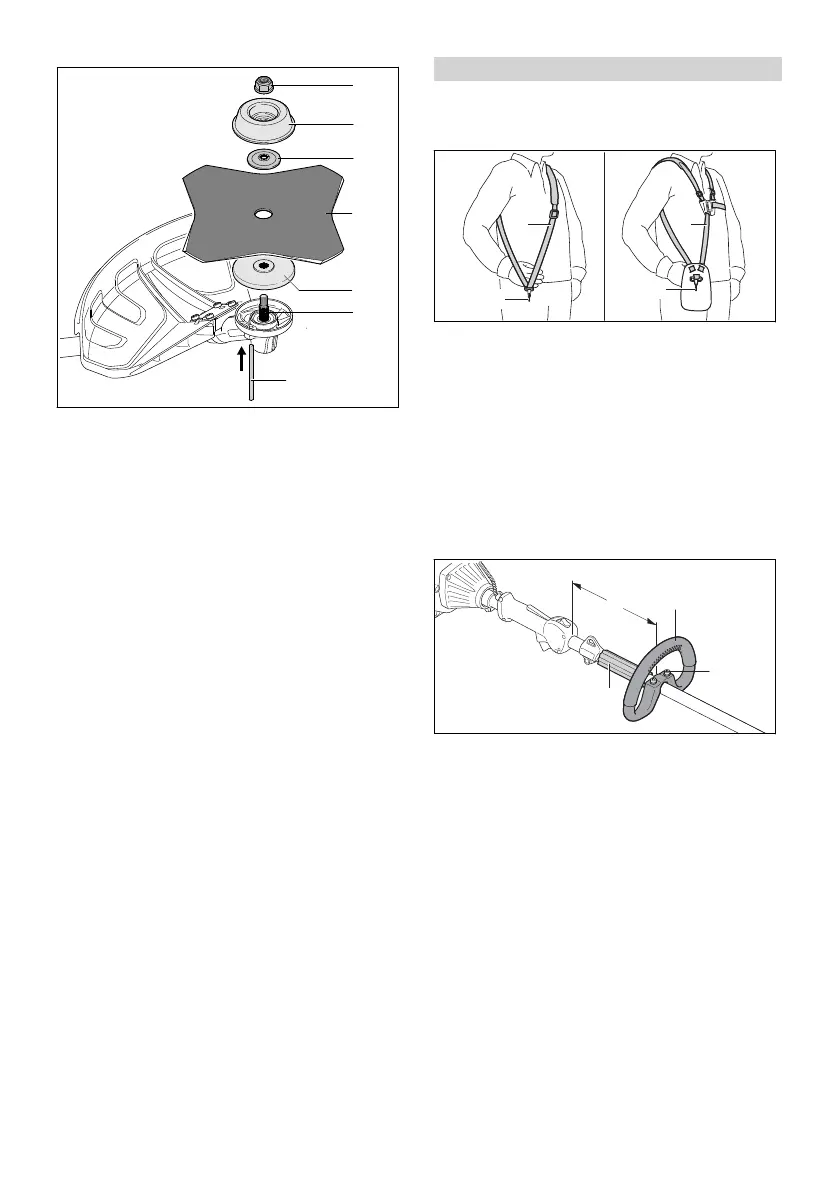
► Place the thrust plate (5) on the shaft (6) so
that its smaller diameter faces up.
► Place the metal cutting attachment (4) on the
thrust plate (5). If you are fitting a circular saw
blade or a grass cutting blade with more than
4 cutting edges: Its cutting edges must face in
the same direction as the arrow on the deflec‐
tor.
► Place the thrust washer (3) on the metal cut‐
ting attachment (4) so that its raised side faces
up.
► Place the rider plate (2) on the thrust washer
(3) so that its closed side faces up.
► Insert the stop pin (7) in the bore as far as
stop and hold it depressed.
► Rotate the metal cutting attachment (4) coun‐
terclockwise until the stop pin (7) engages in
position.
The shaft (6) is now blocked.
► Fit the nut (1) counterclockwise and tighten it
down firmly.
► Remove the stop pin (7).
6.7.2 Removing the metal cutting attach‐
ment
► Shut off the engine.
► Insert the stop pin in the bore up to the limit
stop and hold it depressed.
► Rotate the metal cutting attachment clockwise
until the stop pin engages in position.
The shaft is now blocked.
► Unscrew the mounting nut clockwise.
► Remove the fastening parts, metal cutting tool
and pressure plate.
► Remove the stop pin.
7 Adjusting Trimmer for User
7.1 Fitting and Adjusting the Carry‐
ing System
► Put on the shoulder strap (1) or full harness
(3).
► Adjust the shoulder strap (1) or full harness (3)
so that the carabiner (2) is about a hand’s
width below your right hip.
7.2 Adjusting and Setting the Loop
Handle
The loop handle can be set to different positions
to suit the height and reach of the user.
► Shut off the engine.
► Loosen the screws (2).
► Move the loop handle (1) to the required posi‐
tion and check that the following conditions
are met:
–
The bump guard (3) fits between the loop
handle (1) and carrying ring.
–
Distance (a) is no more than 30 cm.
► Tighten down the screws (2) so that the loop
handle (1) cannot be rotated on the shaft.
7 Adjusting Trimmer for User English
0458-891-0101-A 13
 Loading...