FS 240, FS 240 C, FS 240 R, FS 240 RC, FS 260 R, FS 260 RC
English
18
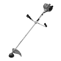
Adjusting and Securing the Loop Handle
The loop handle can be adjusted to suit
the height and reach of the operator and
the application by changing
distance (A).
Recommendation: distance (A):
about 30 cm (12 in)
N Slide the handle to the required
position.
N Line up the loop handle (4).
N Tighten down the screws until the
loop handle can no longer be
rotated on the drive tube. If no
barrier bar is fitted – lock the nuts if
necessary.
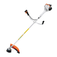
Polymer Version
For position of carrying ring see "Main
Parts".
N Push the carrying ring (1) over the
drive tube.
N Insert the M5 nut in the hex recess
in the carrying ring.
N Fit the M5x14 screw.
N Line up the carrying ring.
N Tighten down the screw firmly.
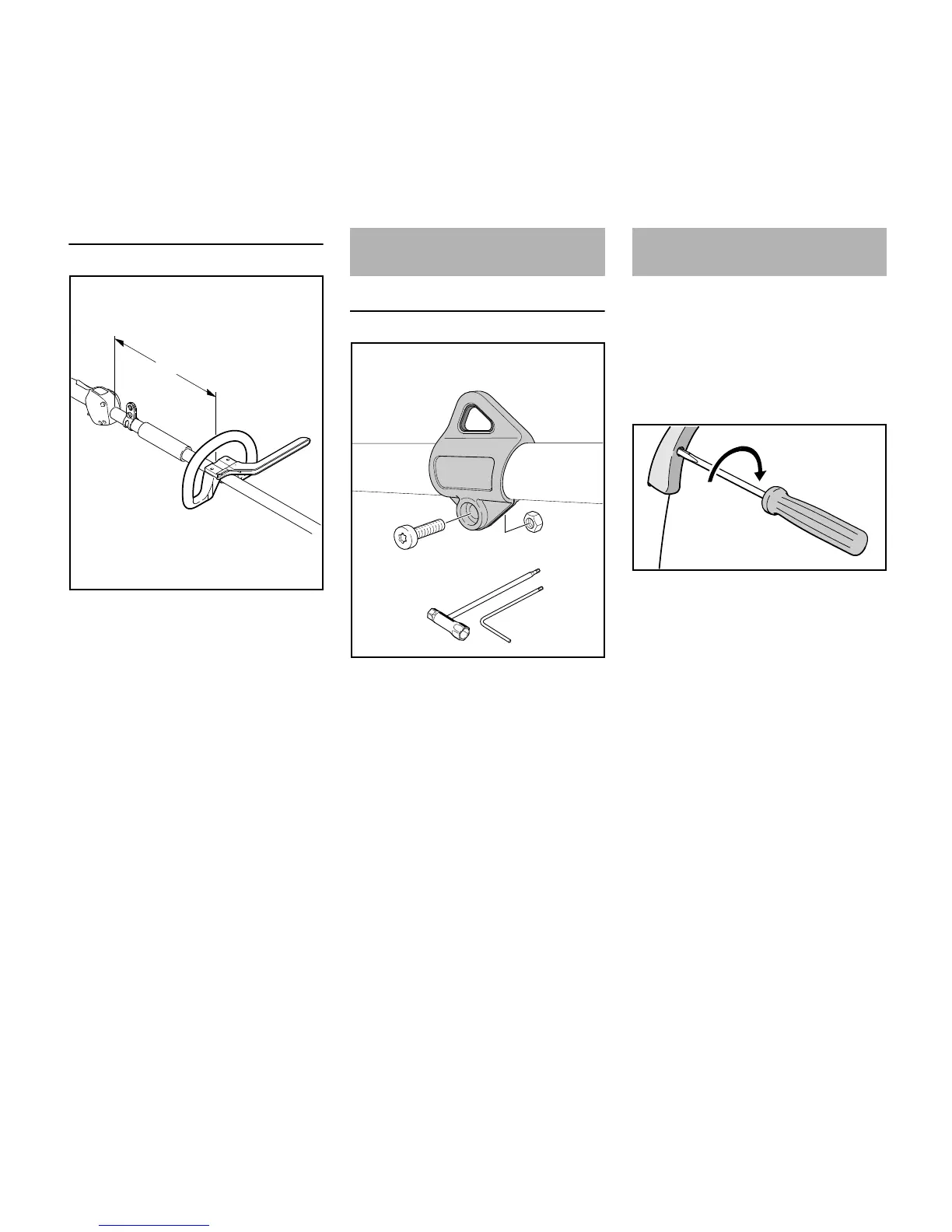
It may be necessary to correct the
adjustment of the throttle cable after
assembling the machine or after a
prolonged period of operation.
Adjust the throttle cable only when the
unit is completely and properly
assembled.
N Set the throttle trigger to the full
throttle position.
N Carefully rotate the screw in the
throttle trigger in the direction of the
arrow until you feel initial resistance.
Then rotate it another half turn in the
same direction.
 Loading...