•
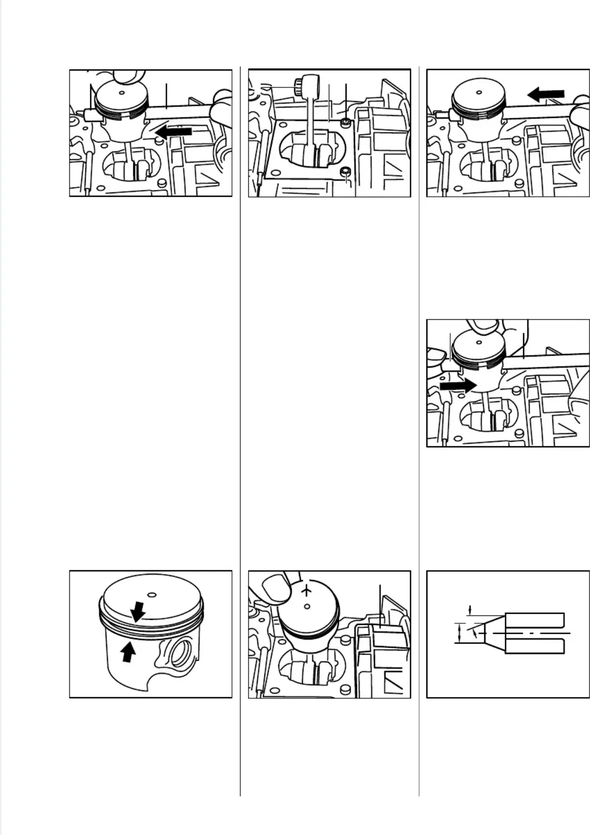
Now use the assembly drift (2)
1110 893 4700 to push the pi-
ston pin (1) out of the piston.
Note:
If the piston pin is stuck, tap
the end of the drift lightly with a
hammer if necessary.Hold the
piston steadyduring this process
to ensure that no jolts are trans-
mitted to the connecting rod.
- Remove piston and take the
needle cage out of the connec-
ting rod.
•
Inspect pistonrings andreplace
if necessary -see 4.6.
•
Thoroughly clean the gasket
seating surface (1).
•
Check that adapter sleeves (2)
are in place. Fit them if necessa-
ry.
•
Lubricate the needle cage (3)
with oil and fit it in the connecting
rod.
•
To simplify assembly, heat the pi-
ston and slip it over the connec-
ting rod.
•
Installed position of piston:
1 = Marking
2 = Flywheel
•
Push the assembly drift, small
diameter first, through the piston
and small end (needle cage) and
line up the piston.
•
Fit the piston pin (1) on the
assembly drift (2) and slide it
into the piston (the pin slides
home easily if the piston is hot).
•
Modify sleeve of installing tool
5910 890 2210 as shown in dra-
wing.
a = 30 degrees
b = Ø 10 mm
2
5
0
R
A
0
3
3
1 2
V
A
2
5
0
R
A
0
3
5
1 2
2
3
V
A
2
5
0
R
A
0
3
7
21
V
A
2
5
0
R
A
0
3
4
V
A
2
5
0
R
A
0
3
8
V
A
2
5
0
R
A
0
3
9
1 2
V
A
2
5
0
R
A
0
5
7
b
a
V
A
4.5.2 Installation
FS 120, 200, 300, 350, 400, 450, FR 350, 450 15
 Loading...