Assemble in the reverse sequence.
- Tighten clamp screws to 2 Nm
(1.5 lbf.ft).
•
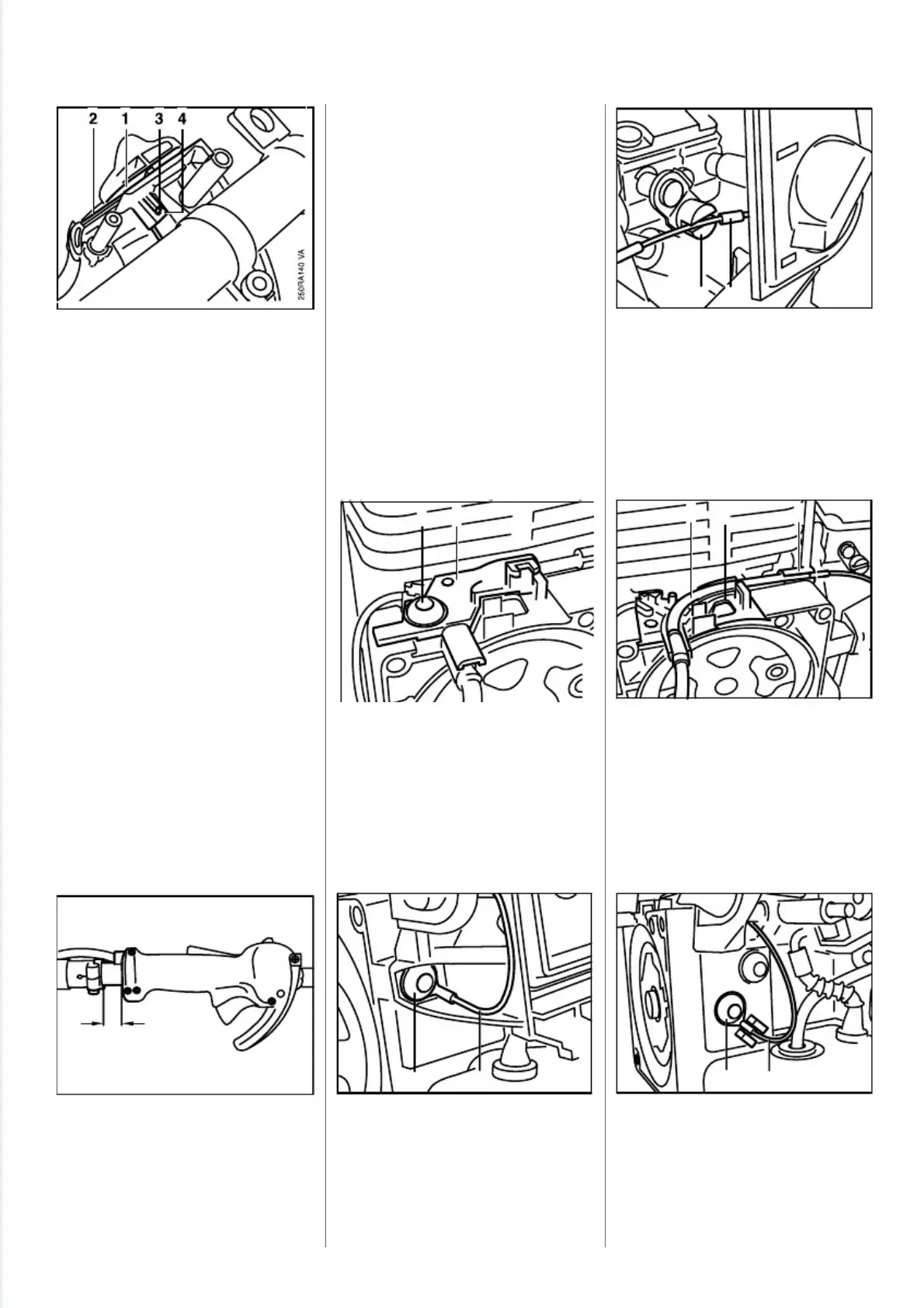
The groove (1) in the slide
control must engage over the
outer edge (2) of the handle
molding.
•
The torsion spring (3) must
engage the recess (4) in the
slide control.
•
On FR 350/450, the distance "a"
between the control handle and
housing must be 20 mm (0.8").
All models
- Remove the shroud - see 4.1.
- Remove clutch housing -
see 9.1 and 11.2.
- Remove the air filter -see 8.1.
- Take throttle cable offthe con-
tact spring -see 7.2 and 7.3.
Note:On FS 120...350, FR 350,
remove spark plug boot and take
ignition lead out of retainers on top
and base of cable guide.
•
Take out the screw (1).
•
Remove top of cable guide (2).
FS 120...350, FR 350
•
Remove screw (1) from
extended throttle cable (2).
•
Disconnect throttle cable nipple
(1) from slotted pin (2) on throttle
lever.
•
Take throttle cable (1) out of
base of cable guide (2) and
retainer (3) on carburetor
housing.
FS 400/450, FR 450
- Remove the air filter housing -
see 8.2.2.
•
Remove screw (1) from
extended throttle cable (2).
7.5 Throttle Cable
7.5.1 Replacing
2
5
0
R
A
1
4
3
12
V
A
2
5
0
R
A
1
4
4
1 2 3
V
A
2
5
0
R
A
1
4
1
V
A
1 2
2
5
0
R
A
1
4
5
1
2
V
A
2
5
0
R
A
1
4
2
1
2
V
A
2
5
0
R
A
2
3
7
a
V
A
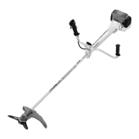
36 FS 120, 200, 300, 350, 400, 450, FR 350, 450
 Loading...