83FS 240 C, FS 260 C, FS 360 C, FS 410 C, FS 460 C-M
Installation
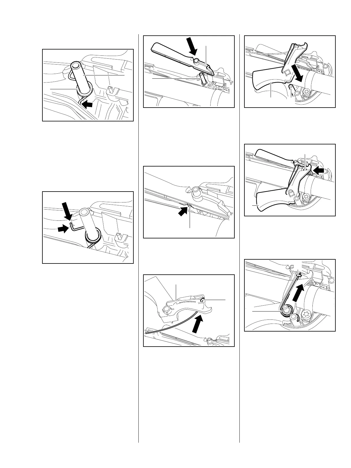
Shown without drive tube assembly
for a better view.
: Push torsion spring (1) onto the
post (2) so that the end that is
angled downward rests against
the ridge (arrow) on the left
: Use a suitable tool to press the
upper end (arrow) of the torsion
spring toward the handlebar and
hold it there
5904RA267 TG
1
2
5904RA268 TG
: Slide throttle interlock (1) onto
the post (2)
– Release upper end of the torsion
spring
: Torsion spring (1) must lie in the
notch (arrow)
: Thread throttle cable (1) into
throttle trigger (2)
– Turn throttle trigger by 90°
counterclockwise
5904RA269 TG
2
1
5904RA270 TG
1
5904RA393 TG
1
2
: Slide throttle trigger (1) onto the
post (2)
: Orient throttle trigger (1) so that
the lug (2) engages the trigger
interlock (arrow)
: Push torsion spring (1) under the
throttle cable (2)
5904RA271 TG
1
2
5904RA272 TG
1
2
5904RA273 TG
1
2
 Loading...