ENES
15
PTNOSVFIDAELBGUK
0478 121 9804 A - EN
● Carry out assembly work on
level, flat and solid ground.
Check scope of delivery before
assembly.
● Assemble the grass catcher box
and install the lower
handlebars (D) – observe the
specified tightening torque.
● Position the upper handlebar onto the
lower handlebars at the required height
and hold. (Ö 7.3)
● Install the upper handlebar and
insert the power cable into the
cable guide (J) as shown and
fasten to the handlebar using the
cable clips (K).
● Attach the grass catcher box. (Ö 7.1)
7.1 Grass catcher box
Attaching:
● Open the discharge flap (1) and
hold it open.
● Attach the grass catcher box (2) to the
mountings (3) on the rear of machine by
means of the locating lugs.
● Close the discharge flap (1).
Detaching:
● Open the discharge flap (1) and hold it
open.
● Lift the grass catcher box (2) and
remove it rearwards.
● Close the discharge flap (1).
7.2 Level indicator
The upper part of the grass catcher
box features a level indicator (1).
The flow of air that is created by the rotary
movement of the mowing blade and is
responsible for filling the grass catcher box
raises the level indicator (2):
The grass catcher box is filled with
clippings.
When the grass catcher box is full, this
flow of air is reduced and the level
indicator drops (3):
● Empty filled grass catcher box (Ö 10.5).
7.3 Handlebar
1 Folding down the upper handlebar:
Transport position – for space-saving
transport and storage:
● Unscrew rotary handles (1) until they
can be moved freely and fold down
upper handlebar (2) forwards. Make
sure that the electric cable is not
damaged.
Working position – for pushing the
machine:
● Fold up upper handlebar (2) rearwards
and hold with one hand.
● Tighten rotary handles (1).
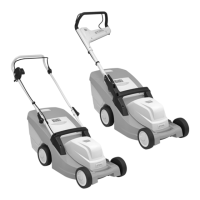
2 Height adjustment:
The upper handlebar can be installed at
2 heights:
● Remove rotary handles (1) and remove
screws (3).
● Adjust upper handlebar (2) to the
desired height:
Bore A – high position
Bore B – low position
● Insert screws (3) through bores in lower
and upper handlebars, tighten rotary
handles (1).
7.4 Central cutting height
adjustment
Five different cutting heights can be
set.
Level 1:
lowest cutting height (25 mm)
Level 5:
highest cutting height (65 mm)
Setting cutting height:
● Press detent lever (1) outwards and
hold.
● Set the required cutting height by
moving the machine upwards and
downwards.
● Release detent lever (1) and allow it to
engage.
7. Controls
2
3
4
5
6
Danger of pinching!
The upper handlebar can fold down
when the rotary handles are
released. For this reason, always
hold the upper handlebar (2) with
one hand at its highest point when
you loosen the rotary handles.
7
8
9