5
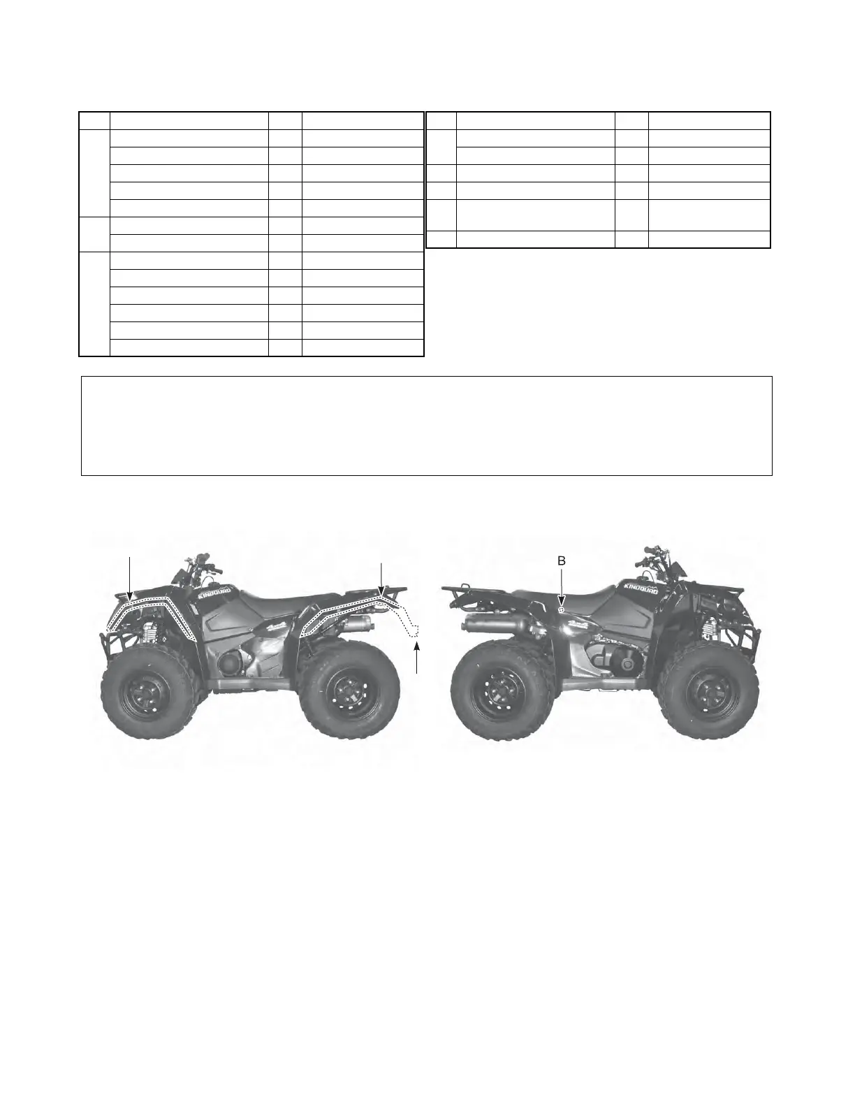
LOCATION OF PARTS
Check all the components which have been removed from the base of the crate.
Parts listed above are installed respectively into the position as follows.
Item Part Name Q’ty Remarks
A
Mud guard front fender 2 Right and Left
Fastener 10
Screw 2 5 × 25 mm
Washer 2 OD:20.0 ID:5.5
Rubber cushion (with nut) 2 5 mm L:21.0
B
Battery holder 1
Flange bolt 2 6 × 16 mm
C
Mud guard rear fender 2 Right and Left
Fastener 10
Screw 2 5 × 20 mm
Screw 2 5 × 25 mm
Washer 4 OD:20.0 ID:5.5
Rubber cushion (with nut) 4 5 mm L:21.0
Item Part Name Q’ty Remarks
D
Reflex reflector 2 For E-17
Flange nut 2 5 mm
E Warning label set 1 For E-17
F DVD 1 For E-17
G
Battery electrolyte
container
1
HOwner’s manual 1
NOTE:
• Item B and H are located in the box under the seat (H: For E-24, 28).
• The parts shown as Item A, C, D, E and F in the above table are supplied for limited markets.
• Please hand over the parts shown as Item F and H in the above table to your customer together with vehi-
cle.

 Loading...


