499231
12 | IV-50 EC
8.4 Motor Controls
◊ The product fan speed can be either:
◊ Option 1: On / off, set to run at maximum speed when powered
OR
◊ Option 2: Variable speed, adjusted by an external control signal
◊ See 8.5.1 Connection Diagram - Control voltage for external speed adjust options
◊ Option 1 is the factory setting
◊ Contact Systemair if you wish to use a lower maximum fan speed than factory default without variable speed control.
◊ To activate Option 2, variable speed control, do the following three steps:
1. Observe all safety information and preconditions.
2. Remove the red jumper in the electrical terminal between ‘Control Voltage’ 5 (yellow) & 6 (blue) and place it in
the terminal end cap.
3. Connect the desired control signal.
a. See 8.5.1 Connection Diagram for control options and wiring details.
◊ DO NOT use any buttons or switches located in the motor drive access cap.
o Contact Systemair for further information.
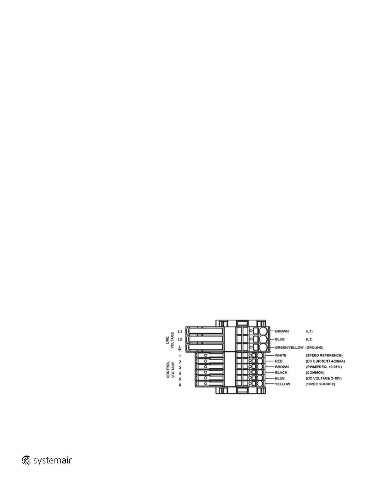
8.5 Field Connections
◊ Check that the data on the nameplate matches the connection data.
◊ Complete the electrical connection according to the connection diagram.
◊ Lay the connection cables in the terminal box in such a way that allows the cover of the terminal box to be closed without resistance.
◊ Screw the lid of the terminal box to 18 Inch-Lbs.
◊ Connect the cable end in a dry environment.
8.5.1 Connection Diagram
◊ All connections shall be made using the supplied quick connect lever-action terminals.
Line voltage (L1, L2, ):
• Field power connections are to be made in the electrical
box
• The grounding terminal is electrically connected to the
unit through the DIN rail.
Control voltage (1-6):
The speed can be adjusted by the input signals labeled
‘control voltage’, see Section 8.4 for set up:
• DC voltage (blue, black): 2 to 10V DC [tolerance: +10%]
• DC current (red, black): 4 to 20mA DC [tolerance: +10%]
• Frequency duty-cycle, PWM (brown, black): 10 to 95%
• Voltage: 10 to 24Vpk [tolerance: -5%/+10%]
• Frequency: 80Hz [tolerance: +/-2.5%]
• The motor will turn off if imposed signals are lower than
2V DC, 4mA DC or 10%.
Speed reference connection:
• The fan RPM may be monitored through the speed
reference signal explained below.
 Loading...