8
| Electrical connections
7 Electrical connections
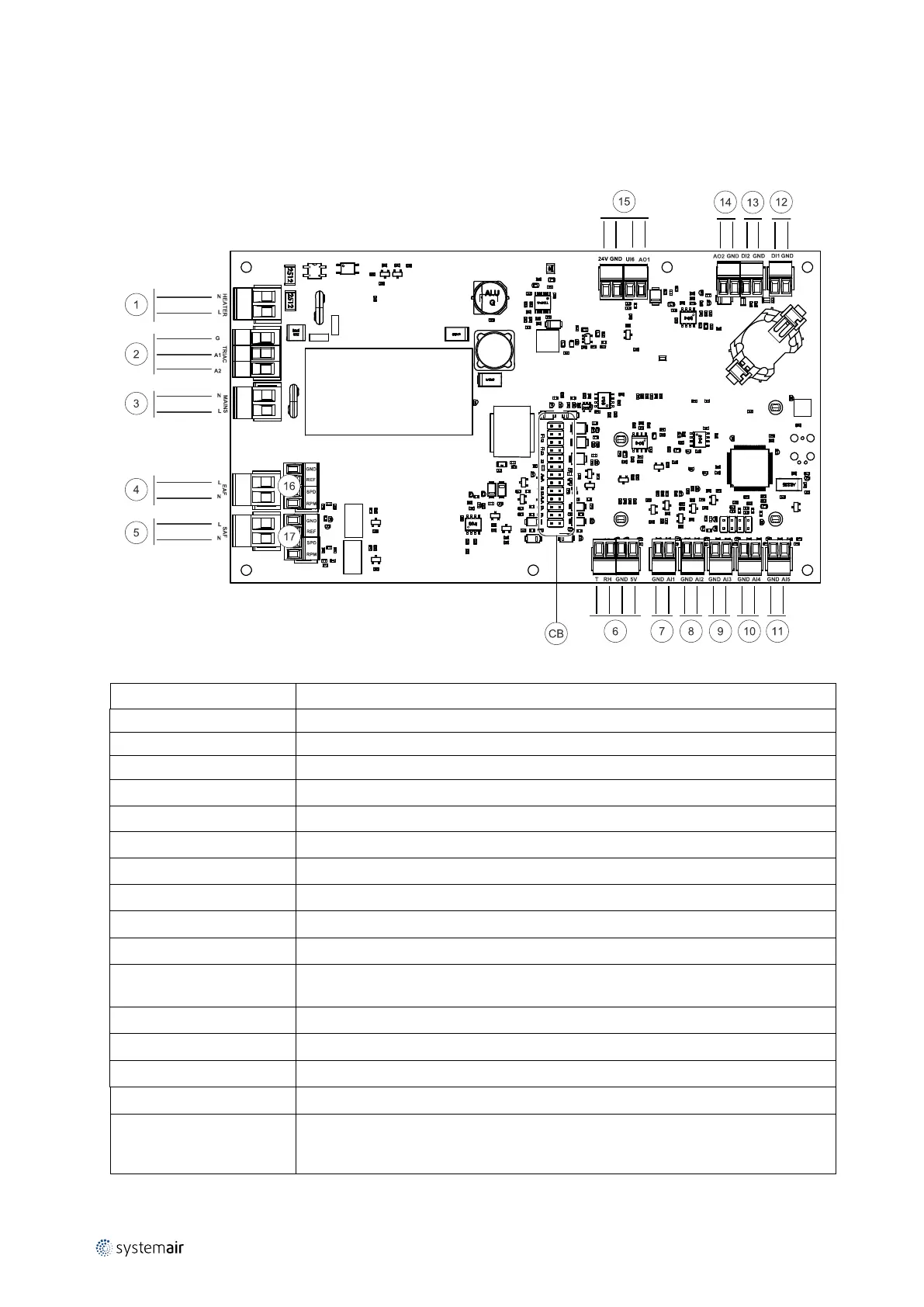
7.1 Main circuit board layout
The SAVE VSR 300/500 is equipped with built-in regulation and internal wiring.
Fig. 6 Main circuit board connections
Position Description
CB
Connection to the external connection box
1
Terminals for a heater
2
Terminals for a TRIAC
3
Terminals for the mains power supply
4
Terminals for power supply of extract air fan
5
Terminals for power supply of supply air fan
6
Terminals for internal relative humidity/temperature sensor
7
Analog input 1 — Outdoor air sensor
8
Analog input 2 — Supply air sensor
9
Analog input 3 — Freely configurable
10
Analog input 4 — Freely configurable / Overheat temperature sensor (units with
heater)
11
Analog input 5 — Freely configurable
12
Digital input 1 — Rotor guard sensor (only for VSR, VTR models)
13
Digital input 2 — Freely configurable / Cooker hood (VTR 150/K unit)
14
Analog output 2 — Freely configurable / Electrical heater controller (VTC 700 unit)
15
Analog output 1 — Rotary heat exchanger control signal (for VSR, VTR type models) /
Damper control signal (for VTC, VSC type models), UI6 — Bypass damper feedback
signal (for VTC, VSC type models)
333547 | v1.1
 Loading...