26
|
Service
4.4 Electrical connections
The SAVE VSR 300/500 is wired internally from factory.
The electrical connection box is on top of the unit behind
a cover plate.
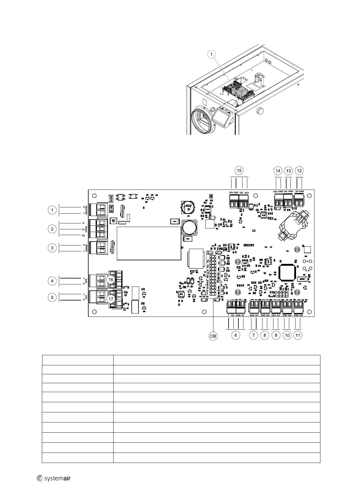
1. Main print card
4.4.1 Main circuit board layout
The SAVE VSR 300/500 is equipped with built-in regulation and internal wiring.
Fig. 6 Main circuit board connections
Position Description
CB
Connection to the external connection box
1
Terminals for a heater
2
Terminals for a TRIAC
3
Terminals for the mains power supply
4
Terminals for power supply of extract air fan
5
Terminals for power supply of supply air fan
6
Terminals for internal relative humidity/temperature sensor
7
Analog input 1 — Outdoor air sensor
8
Analog input 2 — Supply air sensor
9
Analog input 3 — Freely configurable
| v1
 Loading...