Accessories
|
37
4. Configure control signal. Go to Service > Output > DIGITAL menu. Select the digital output to which the ground
heat exchanger is connected. Example if it is connected to DO3 on the connection board, then select DIGITAL OUT-
PUT 3 and select Start/Stop Circ. Pump, Y4 Extra Controller from the output type list.
5. Configure internal outdoor temperature sensor as extra controller temperature sensor. Go to Service > Input >
ANALOG > ANALOG INPUT 1 and change input configuration from Outdoor Air Temp. Sensor (OAT) to Extra
Controller Temp. Sensor (ECT).
6. After sensor configuration is changed, select analog input to which the newly installed duct temperature sensor
(OAT) is connected and configure input as Outdoor Air Temp. Sensor (OAT).
5.3.5 Change-over coil for heating/cooling function
Change-over coil can be used for both heating and cooling based on the demand.
Important
The change-over (heating/cooling) system can be implemented in many different ways and may vary in
each household. This description explains the most common solution for connecting and controlling heating
and cooling with a water coil and a heat pump.
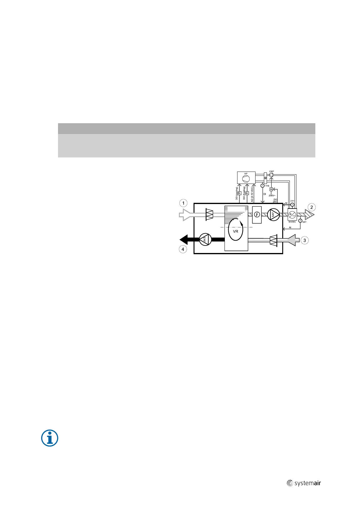
• WH/WC — change-over coil
• FPT — frost protection sensor (optional)
• SAT — supply air temperature sensor
• THS — thermostat for sensing if the temperature of
heating/cooling fluid in the system is right (optional)
• HP — heat pump (or other device for heating and
cooling)
• CWP — water pump
• RL — relay
• 1 — Outdoor air
• 2 — Supply air
• 3 — Extract air
• 4 — Exhaust air
Component/product — Article number:
• Relay 24V with socket — 159484
• Duct sensor -30-70C (SAT) — 211524
• Surface sensor -30-150C (FPT) — 211523
Installation and connection
1. Install change–over coil in the duct. Install a water pump if necessary. The turning on and off of water pump should
be controlled with a relay (RL). Connect the relay to any free digital output and 24 V on the connection board. Then
connect the power supply and a water pump (CWP) to the relay.
2. Connect a control signal wire (if available) of the heat pump (HP) to any free digital output and 24 V on the connec-
tion board.
3. Connect cooling and heating start signal wires to any free digital outputs on the connection box. Relays (RL) must be
used.
4. The frost protection sensor (FPT) should be strapped on a surface on the return water pipe. Connect the frost protec-
tion sensor (FPT) sensor to any free analog input.
5. An internal supply air temperature sensor (SAT, default connection AI2 on the main circuit board) must be replaced
by a duct temperature sensor which can be acquired as an accessory. A duct temperature sensor must be installed in
the duct after heater/cooler. Connect the duct temperature sensor to analog input 2 (AI2) replacing the internal sup-
ply air temperature sensor.
Note:
A duct temperature sensor can be connected to analog inputs 6–7 on the connection board for better
access and then configured as a supply air temperature sensor. However the internal supply air
temperature sensor must be disabled in the control panel first.
| v1
 Loading...