M850-00
T855 Circuit Operation
B2.9
Copyright TEL 31/09/98
2.9 Microcontroller
(Refer to the microcontroller circuit diagram (sheet 8) in Section 6.3.)
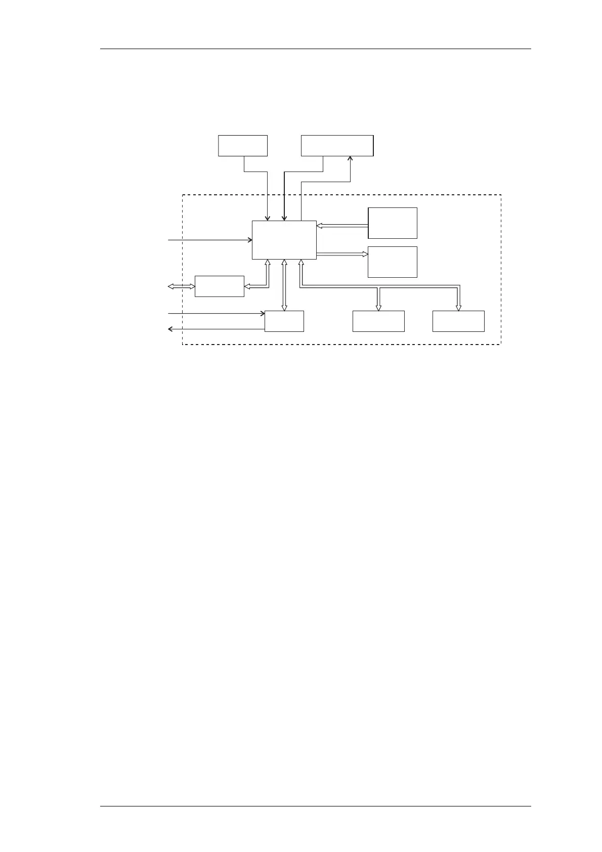
Figure 2.5 T855 Microcontroller Block Diagram
Overall system control of the T855 is accomplished by the use of a member of the 80C51
family of microcontrollers (IC810) which runs from internal ROM and RAM. Four ports
are available for input/output functions.
Non-volatile data storage is achieved by serial communication with a 16kBit EEPROM
(IC820). This serial bus is also used by the microcontroller to program the synthesiser
(IC740).
The main tasks of the microcontroller are as follows:
• program the synthesiser;
• interface with the PGM800Win programming software at 9600 baud via the
serial communication lines on D-range 1 (PL100) & D-range 2;
• monitor channel change inputs from D-range 2;
• generate timing waveforms for CTCSS detection;
• coordinate and implement timing control of the receiver.
Channel
Select
Port
Auxiliary
Output
Port
Microcontroller
12.8MHz
Clock
Microcontroller Cavity
Audio In
Speech
External
Serial
Port
EEPROM
Synthesiser
CTCSS
Decoder
Converter
5V Reset
5V Digital
Regulator
Watchdog Timer
& LVI
Watchdog
 Loading...


