B4.6
T855 Functional Testing
M850-00
31/09/98 Copyright TEL
4.7 Noise Mute (If Linked In)
Rotate RV230 (front panel gating sensitivity) fully anticlockwise.
Apply an on-channel signal from the RF generator at a level of -110dBm with
±3kHz deviation (±2.4kHz) [±1.5kHz] at 1kHz.
Increase the RF level in 1dB steps, checking that the mute opens for an RF input
level of approximately -105dBm.
Turn the RF off and check that the mute closes.
Rotate RV230 clockwise and check that the mute opens.
Reset RV230 to give the required opening sinad.
Caution:
Some RF generators can cause a false opening of the mute because the
generator produces a burst of noise when the attenuation range
changes. To correct the problem you will have to change generators.
4.8 RSSI (If Fitted)
Apply an on-channel signal from the RF generator at a level of -110dBm with
±3kHz deviation (±2.4kHz) [±1.5kHz] at 1kHz.
Using a high impedance DMM, check that the RSSI output voltage on pin 5 of
D-range 1 (PL100) is 2V (nominal).
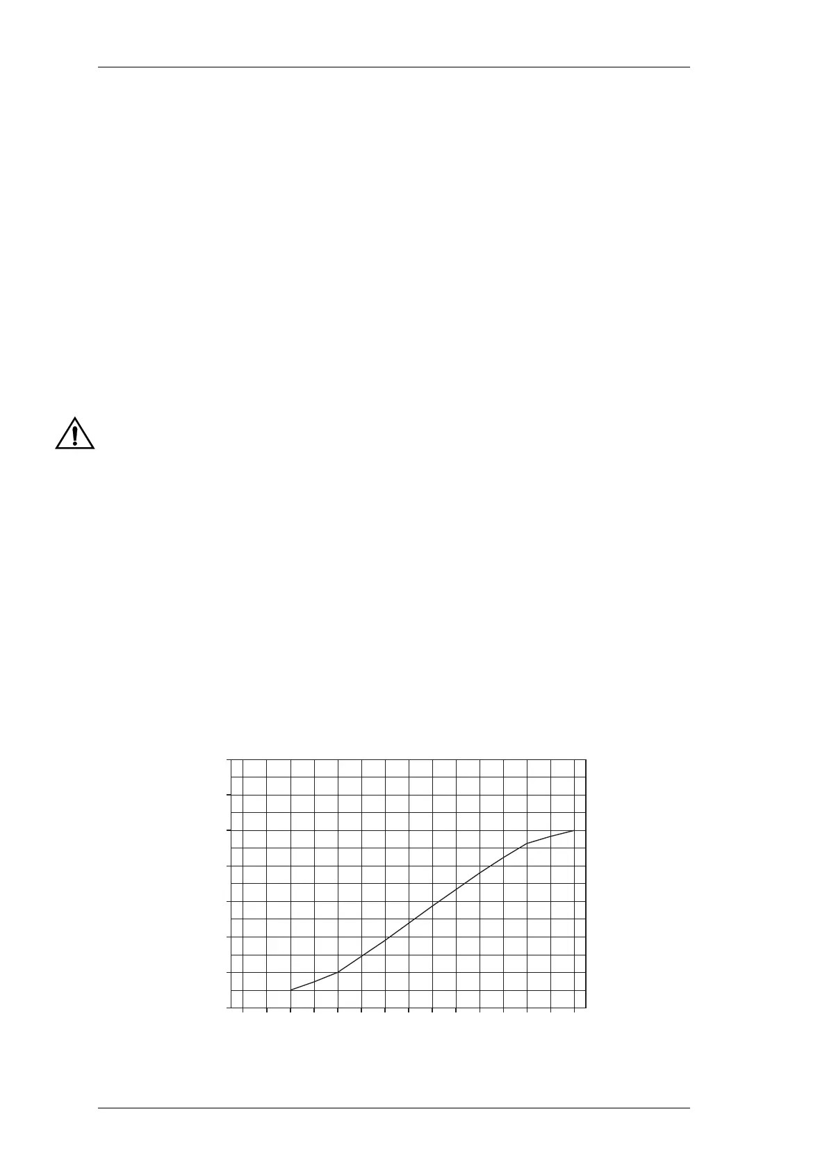
Vary the RF level in 5dB steps and check that the RSSI output voltage changes at a
rate of approximately 10dB/V over the range of -115dBm to -70dBm (refer to Fig-
ure 4.2 for RSSI voltage vs signal strength).
Figure 4.2 T855 RSSI Voltage vs Signal Strength
RF Level (dBm)
-130 -120 -110 -100 -90 -80 -70 -60
1
2
3
4
5
6
7
8
RSSI Voltage