TA2922 Universal Line Interface Service Manual 9
© Tait Electronics Limited March 2010
1.3 Connections
The following tables summarize the signals used for the universal line interface
board on the internal options connector (SK2) and the external options connector
(SK1).
The signals on SK1 are dependant on the configuration of the matrix. Refer to
“SK1 I/O signal configuration” on page 26.
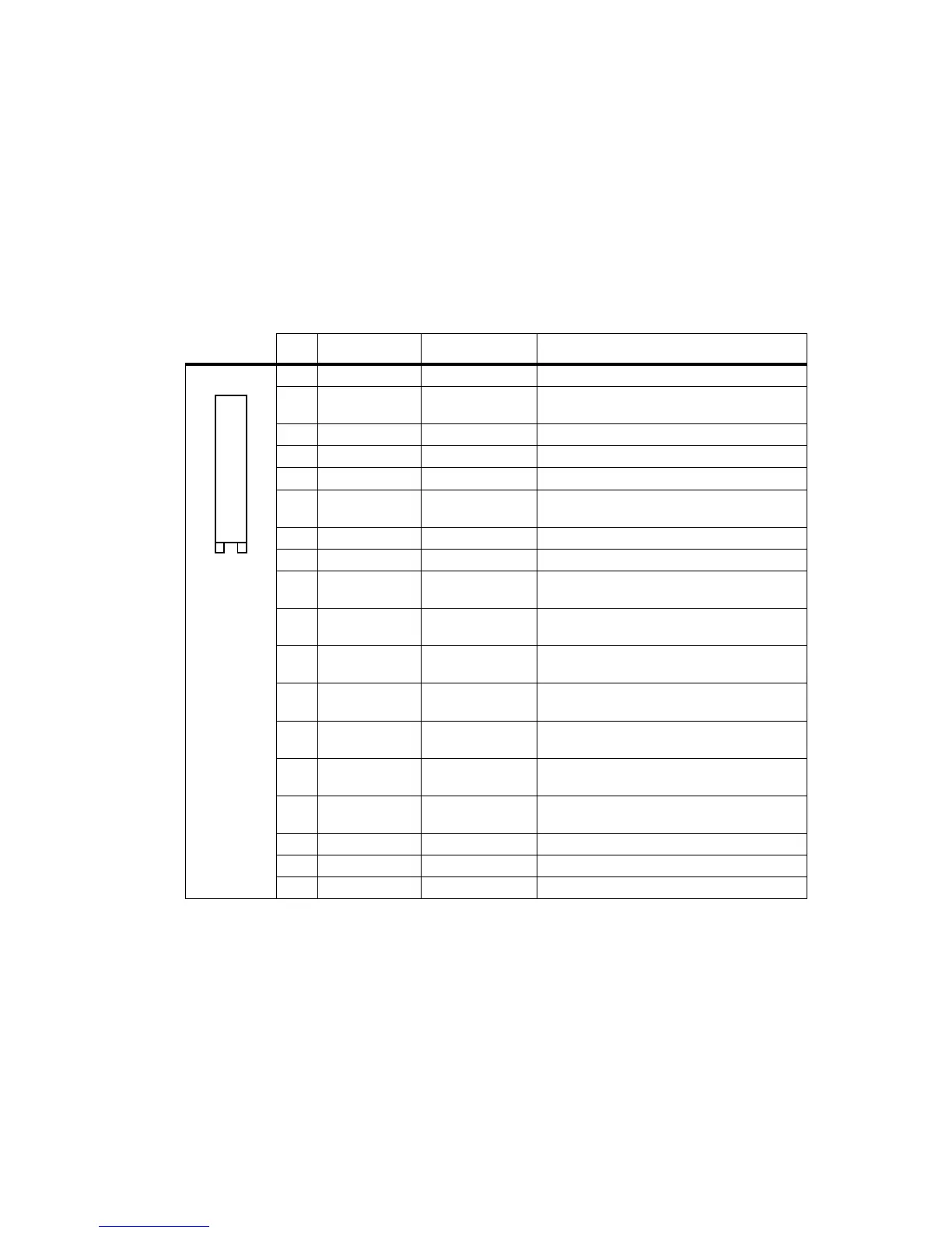
Internal options connector (SK2)
Pin Radio Signal Signal Description
1 13V8_SW
+13V8_SW
switched 13V8 supply from the radio
2 AUD_TAP_OUT AUDIO_TAP_OUT
Programmable tap point out of the receive or
transmit audio chain.
3AGND AGND
analogue ground
4 AUX_MIC_AUD AUX_MIC_AUD
Electret auxiliary external mic
5 RX_BEEP_IN RX_BEEP_IN
beep audio to radio (not implemented)
6 AUD_TAP_IN AUD_TAP_IN
Programmable tap point into the receive or
transmit audio chain
7 RX_AUD RX_AUD
volume controlled Rx audio
8 RSSI RSSI
analogue receive signal strength indicator
9 IOP_GPIO1 GPIO1 Radio PTT
IOP_GPIO1 to/from the radio
3V3 logic level, 5V tolerant
10 IOP_GPIO2 GPIO2 Radio Busy
IOP_GPIO2 to/from the radio
3V3 logic level, 5V tolerant
11 IOP_GPIO3 GPIO3
IOP_GPIO3 to/from the radio
3V3 logic level, 5V tolerant
12 IOP_GPIO4 GPIO4 Disable Line
Interface
IOP_GPIO4 to/from the radio
3V3 logic level, 5V tolerant
13 IOP_GPIO5 GPIO5
IOP_GPIO5 to/from the radio
3V3 logic level, 5V tolerant
14 IOP_GPIO6 GPIO6
IOP_GPIO6 to/from the radio
3V3 logic level, 5V tolerant
15 IOP_GPIO7 GPIO7
IOP_GPIO7 to/from the radio
3V3 logic level, 5V tolerant
16
DGND
—
analogue ground
17
IOP_RXD
IOP_RXD
asynchronous serial port - receive data
18
IOP_TXD
IOP_TXD
asynchronous serial port - transmit data
B
D
F
H
J
1!
1#
1%
1&
C
E
G
I
1)
1@
1$
1^
1*
top view
 Loading...