TB7100 Installation Guide Connections 23
© Tait Electronics Limited March 2006
2.2 Internal Connectors
2.2.1 Transmitter and Receiver Connectors
The internal connectors of the transmitter and receiver are the same for both
modules.
Note Whilst the internal connectors may be physically similar, the sig-
nals on the user interface connectors are different for the transmit-
ter and the receiver.
RF Connectors The RF connectors of the transmitter and the receiver are N-type
connectors with an impedance of 50
Ω.
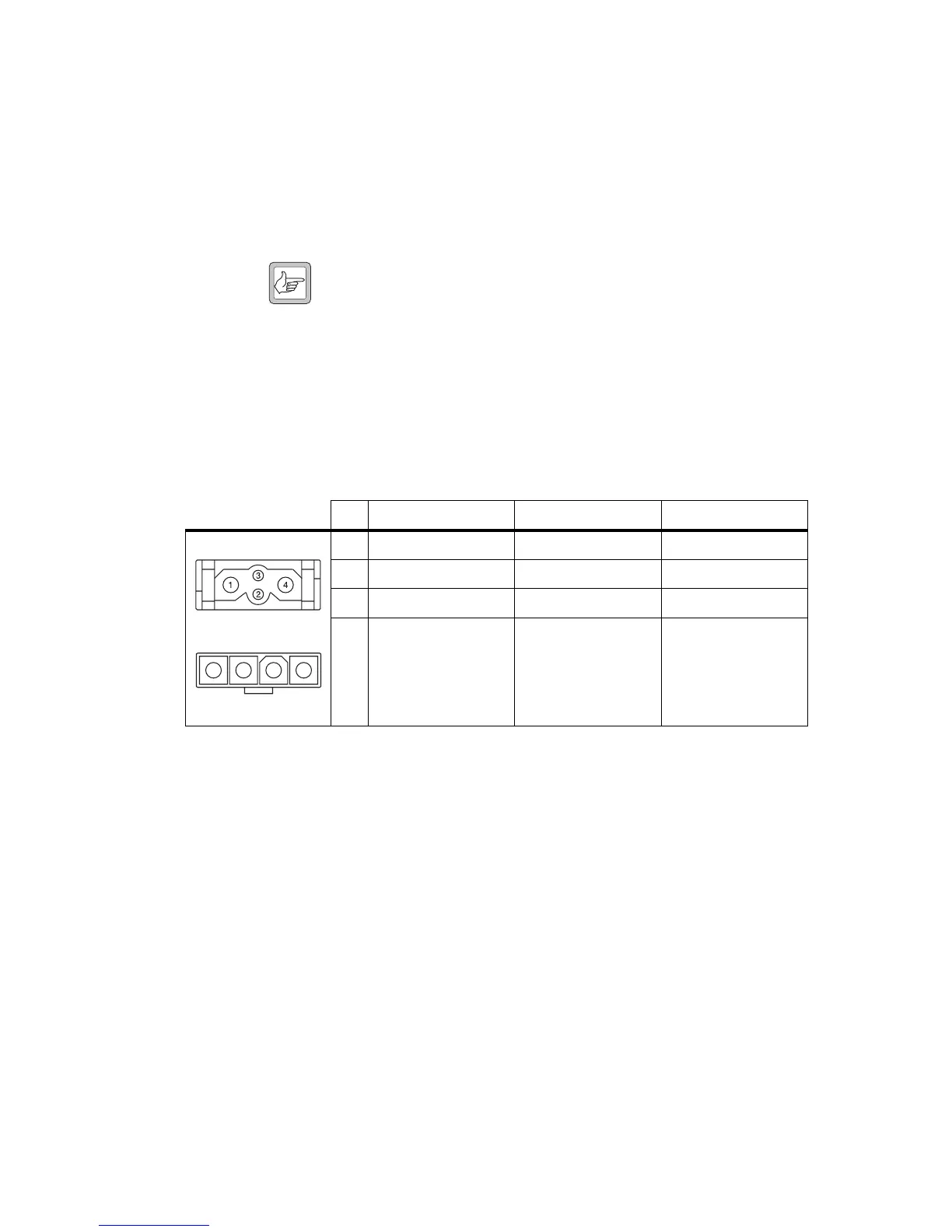
DC Power
Connectors
The DC power connectors of the transmitter and the receiver are the
interface for the primary 13.8V power source. There are different
DC power connectors for the 50W/40W and 25W versions.
Pin Signal name Signal type Notes
1AGND ground
2 SPK– analog output not connected
3 SPK+ analog output not connected
4 13.8VDC DC power input
external view
50W/40W
1 2 3 4
external view
25W

 Loading...


