Home
TCL
Air Conditioner
TAC-07CS
TCL TAC-07CS User Manual
5
of 1
of 1 rating
138 pages
Give review
Manual
Specs
To Next Page
To Next Page
To Previous Page
To Previous Page
Loading...
TCL
Air Conditioner Service Manual
29
INDOOR UNIT
T
A
C-0
7
CS/K,
T
A
C-0
7
CSH/K,
T
A
C-0
7
CSC/K,
T
A
C-0
7
CHSC
/
K
,
T
A
C
-
09CS
/
K,
T
A
C
-
09
C
H
S/K,
T
A
C-09CSC
/
K
,
T
A
C
-09
C
HS
C/
K,
T
A
C
-12
C
S
/
K,
T
A
C
-12
C
HS
/
K,
T
A
C
-12
C
S
C/
K,
T
A
C
-12
C
H
C/
K,
1
2
3
5
14
6
7
8
9
10
15
16
17
18
19
20
21
22
23
24
25
26
27
11
12
13
4
28
29
30
28
30
Table of Contents
Table of Contents
1
Service Manual
1
Important Notice
2
Technical Specifications
3
Product Dimensions
8
Cooling Only
9
Heat Pump
9
Refrigerating Cycle System
9
Additional Refrigerant Charge
10
Max. Height Difference
10
Max. Refrigerant Piping Length
10
Evacuation Procedures (Air Purge)
11
Guaranteed Voltage, Air Flow
12
How to Measure the Indoor Air Wet-Bulb/Dry-Bulb Temperature Difference
12
Mains Readings
12
Performance Curves
12
Outdoor Low Pressure and Outdoor Unit Current Cool Operation
13
HEAT Operation
15
Operation Details
16
Remote Controller
16
Electronic Controller
17
Safety Control
17
“COOLING” Mode Operation
17
“I Feel” Mode Operation
17
“DRY” Mode Operation
18
“HEATING” Mode Operation (Only Available for Heat Pump)
18
Assistant Thermistor Function
19
Defrost
19
4-Way Valve Control
20
Auto Fan Speed Control
20
Fan Motor Control
20
“SLEEP” Mode
20
Auto Restart Function
21
Auto Vane Operation Control
21
Emergency Test Operation
21
Timer Operation
21
Auto-Restart Presetting
22
Failure Display and Handling
22
Wiring Diagram - TAC-07CS/K, TAC-09CS/K, TAC-12CS/K, TAC-07CSC/K, TAC-09CSC/K, TAC-12CSC/K
23
Wiring Diagram - TAC-07CHS/K, TAC-09CHS/K, TAC-12CHS/K, TAC-07CHSC/K, TAC-09CHSC/K, TAC-12CHSC/K
24
Wiring Diagram - TAC-18CS/K, TAC-18CSC/K
25
Indoor Unit
26
Outdoor Unit
26
Wiring Diagram - TAC-18CHS/K, TAC-18CHSC/K
26
Wiring Diagram - TAC-24CS/K, TAC-24CSC/K
27
Wiring Diagram - TAC-24CHS/K, TAC-24CHSC/K
28
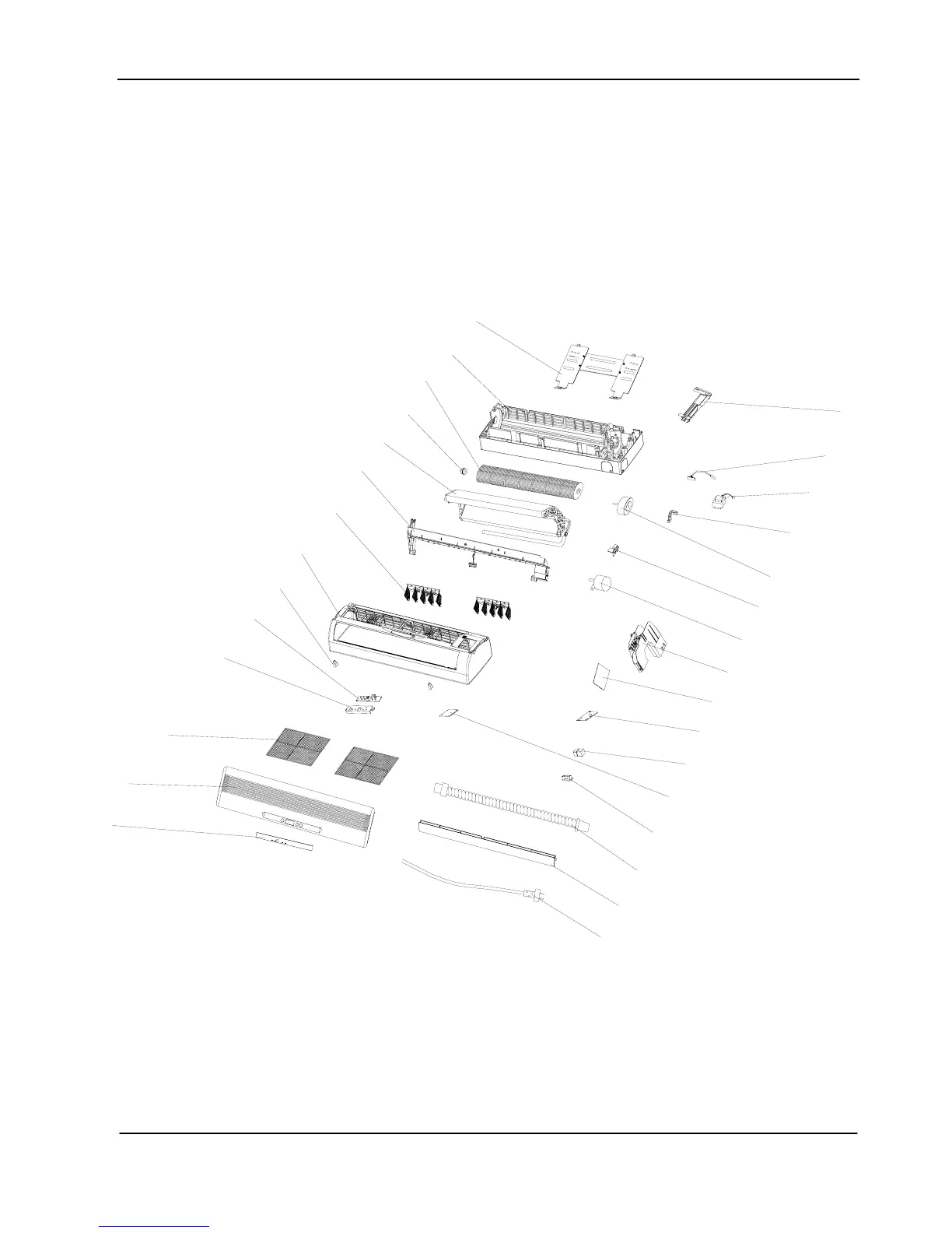
Explosion View
29
Indoor Unit Exploded View
29
Outdoor Unit Exploded View
31
Parts List: Indoor Unit - TAC-07CS/K, TAC-09CS/K
33
Parts List: Indoor Unit - TAC-07CHS/K, TAC-09CHS/K
34
Parts List: Indoor Unit - TAC-07CSC/K , TAC-09CSC/K
35
Parts List: Indoor Unit - TAC-07CHSC/K, TAC-09CHSC/K
36
Parts List: Indoor Unit - TAC-12CS/K, TAC-12CSC/K
37
Parts List: Indoor Unit - TAC-12CHS/K , TAC-12CHSC/K
38
Parts List: Indoor Unit - TAC-18CS/K ,TAC-18CSC/K , TAC-24CS/K , TAC-24CSC/K
39
Parts List: Indoor Unit - TAC-18CHS/K,TAC-18CHSC/K, TAC-24CHS/K, TAC-24CHSC/K
40
Parts List: Outdoor Unit - TAC-07CS/K, TAC-09CS/K
41
Parts List: Outdoor Unit - TAC-07CSC/K, TAC-09CSC/K
42
Parts List: Outdoor Unit - TAC-07CHS/K, TAC-09CHS/K
43
Parts List: Outdoor Unit - TAC-07CHSC/K, TAC-09CHSC/K
44
Parts List: Outdoor Unit - TAC-12CS/K
45
Parts List: Outdoor Unit - TAC-12CSC/K
46
Parts List: Outdoor Unit - TAC-12CHS/K
47
Parts List: Outdoor Unit - TAC-12CHSC/K
48
Parts List: Outdoor Unit - TAC-18CS/K
49
Parts List: Outdoor Unit - TAC-18CSC/K
50
Parts List: Outdoor Unit - TAC-18CHS/K
51
Parts List: Outdoor Unit - TAC-18CHSC/K
52
Parts List: Outdoor Unit - TAC-24CS/K
53
Parts List: Outdoor Unit - TAC-24CSC/K
54
Parts List: Outdoor Unit - TAC-24CHS/K
55
Parts List: Outdoor Unit - TAC-24CHSC/K
56
Annex 2 General
57
Distribution According to Function
58
Distribution According to Installation Type
58
Type of Air Conditioner
58
Four Elements of Air Conditioning
59
Principle of Refrigerating Cycle
59
Principle of Refrigerating: It Is as Follows
59
Refrigerating Cycle
60
The Role of each Cycle
60
Definition of Terms
61
The Term of Unit
62
The Term of Function
63
Evaporation & Condensation Temperature
66
How to Draw a Refrigerating Cycle
66
Mollier Diagram
66
Refrigerant State Transition on Mollier Diagram
66
Discharged Gas State (the State at Compressor Outlet or Condenser Inlet)
67
State of Condensed Liquid
67
State of Expansion Valve Outlet (the State of Evaporator Inlet)
67
Calculation of Refrigerating Cycle
68
Calorie of Condensation
68
Refrigerating Effect
68
Work of Compression
68
Circulation Amount of Refrigerant
69
Coefficient of Performance
69
Mollier Diagram View
71
Discomfort Index (DI)
72
Psychrometric Chart
72
Dewing
73
Relative Humidity in Room to Prevent Inner Area from Dewing
73
Psychrometric Chart View
74
Noise Characteristics
75
Sound Composition
75
Allowable Level of Noise
76
NC Curve
76
Sound Attenuation
76
Calorie from Human Body (Kcal/H. Person)
77
Cooling/Heating Load Calculation
77
Load Calculation
77
Simple Cooling Capacity Calculation Table
79
Aircon Selection
80
Calorie Required Per 1 Square Meter
80
Considerations in Capacity Selection
80
Rough Selection of Capacity
80
The Coordination Coefficient of Cooling Capacity
81
How to Read the Cooling Selection Guide
81
Annex 3 Trouble Shooting
82
Troubleshooting
82
Electric Parts Troubleshooting
83
Electric Wire Capacity
83
External Factors Check
83
Working Power and Voltage Drop
83
Insulation Resistance
84
Internal Factors Check
84
Wire Thickness Required
84
Motor Fan
85
Running Capacitor
85
Thermistor
86
Thermostat
86
Compressor Trouble Diagnosis
87
Electrical Troubles
87
Ground Test
87
Wrong Wiring Check of Compressor Terminal
87
Mechanical Troubles
88
Not Starting
88
Overcurrent Flowing While Running
88
Poor Compression
88
Refrigerant System Troubleshooting
89
Temperature Difference and Current of Suction/Discharge Air in Evaporator
89
Pressure and Temperature of Refrigerant
90
Trouble Finding by Pressure/Temperature
90
Closing of Refrigerant System
91
Pressure Measurement of Low Pressure Side
91
Short of Refrigerant
91
Symptoms and Actions
91
Bad Compression
92
Overcharge
92
Precautions on Repair
93
Summary of Check Items by Cause
93
Product Does Not Operate at All
94
Troubleshooting
94
Room Fan Does Not Operate at All
95
Compressor or Outdoor Fan Does Not Operate at All
96
Up/Down Vane Does Not Operate at All
97
Left/Right Louver Does Not Operate at All
98
Function Setting by Remocon Is Disable
99
Cooling/Heating Conversion Is Disable
100
Installation Fundamentals
101
Leakage/Freon
101
Leakage / Drainage
105
Freon Shortage
110
Cooling Capacity
111
Noise
116
Wiring Mistake
118
Bad Smells & Gases
120
ANNEX 4 R407C Refrigerant - General Information
121
Main Differences between R-407C and R22 Refrigerant
122
Installation Instruction - Wall-Mounted Split Type
123
Characteristics of Refrigerant
124
Strong/Weak Points of Freon
124
Temperature-Pressure Relationships in Saturated Condition
124
Accessory
125
Tools Required
125
Piping Length and Elevation
126
Select the Best Location
126
Split Type Installation
126
Drill a Hole in the Wall
127
How to Fix Installation Plate
127
Flaring Work and Connection of Piping
128
Connection of Piping--Indoor
129
For Right Rear Piping
129
For Left Rear Piping
130
Connection of the Pipes-Outdoor
132
Connecting the Cable between Indoor Unit and Outdoor Unit
133
Connect the Cable to the Outdoor Unit
134
Checking the Drainage and Forming the Pipings
135
Air Purging
136
Air Purging with Vacuum Pump
136
Evacuation
137
Finishing the Job
137
Soap Water Method
137
Evaluation of the Performance
138
Pump down Procedure
138
Settlement of Outdoor Unit
138
Test Running
138
5
Based on 1 rating
Ask a question
Give review
Questions and Answers:
Need help?
Do you have a question about the TCL TAC-07CS and is the answer not in the manual?
Ask a question
TCL TAC-07CS Specifications
General
Brand
TCL
Model
TAC-07CS
Category
Air Conditioner
Language
English
Related product manuals
TCL TAC-07CSA
36 pages
TCL TAC-07CHS
138 pages
TCL TAC-07CS/K
43 pages
TCL TAC-07CSA/M
36 pages
TCL TAC-09CSA
36 pages
TCL TAC-09CHS
138 pages
TCL TAC-09CHSA/GI
19 pages
TCL TAC-09CHSA/F6
40 pages
TCL TAC-09CHSA/XP
40 pages
TCL TAC-09CSD/XA81I
72 pages
TCL TAC-09CHSA/XA31 INVERTER
44 pages
TCL Inverter TAC-09CHSD/XAB1I
58 pages
 Loading...