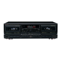
RS・TR575
■CONTENTS
SAFETY PRECAUTlON..■....■.■.._。__..._.._.._.....
ACCESSORlES......._、..__.._._..._騒._、_,_甲.
CONNECTIONS......■.._..........
CAUTlON FOR AC MAINS LEAD._.._._..............
FRONT PANEL CONTROLS.......■.......昌.5..■........巳.._、
PIAYBACK_一■一..._、一..。.一....■..匿一...一1■...1一.ロ.一.一.一ロ_._■.幽.一_._層噂
ABOUTTHEATC FUNCTlON....■.6..巳..■......_._.噂....._、
SEIF・DIAGNOSTIC...._._
DISASSEM BIY I NSTRUCTIONS.6...、.._._._.......5.....5..
HOW TO CHECK THE MAIN P.C.B........__.___
lNSTALLATION OF THE SUB CHASSIS ASS,Y...._....
INSTALLATION OF THE CASSETTE HOIDER ASS,Y..
REPLACEMENTOFTHE FOOT......_...
REPLACEM ENT OF MAI N PARTS......_.__.。.■........._.
WRITING TO EEPROM_......■..■..._
Page
2
2
3
4
5
6,7
8
9
10〜14
14,15
15
16
16
17〜21
22〜24
TROUBLESHOOTING GUIDE.■........__..
MEASUREMENTS AND ADJUSTMENTS.
TERMINAL FUNCTION OF IC.....__.._.
TERMINALGUIDEOFIC,S
TRANSISTORS AND DIODES.......
BLOCK DIAGRAM........
SCHEMATIC DIAGRAM._...
PRNTED CIRCUIT BOARDS._、.._..._..
WIRING CONNECTlON DIAGRAM....._....
REPIACEMENT PARTS UST_......_.......
CABI N ET PARTS lOCAT10N..__
M ECHANISM PARTS LOCATlON......_..
RESISTORS AND CAPACITORS.........._.
PACKAGlNG..__........._
Page
25〜30
31〜33
34〜36
37
38〜40
41〜50
51〜54
55
56,61〜63,66
..... 57,58
59,60
64〜66
66
■SAFETY PRECAUTlON(Thissafety precautlonis applied only ln u.s.A、)
1、
2、
3、
4.
5.
Before servicing,unplug the power cord to prevent an electric shock.
When replacing parts,use only manufacturers recommended components for safety.
Check the、condition of the power cord. RepIace if wear or damage ls evident.
After servicing,be sure to restore the Iead dress,insulation barriers,insulation papers,shields,etc.
Before retuming the serviced equlpment to the customer,be sure to make the foowing insulation resistance
test to prevent the customer from being exposed to a shock hazard.
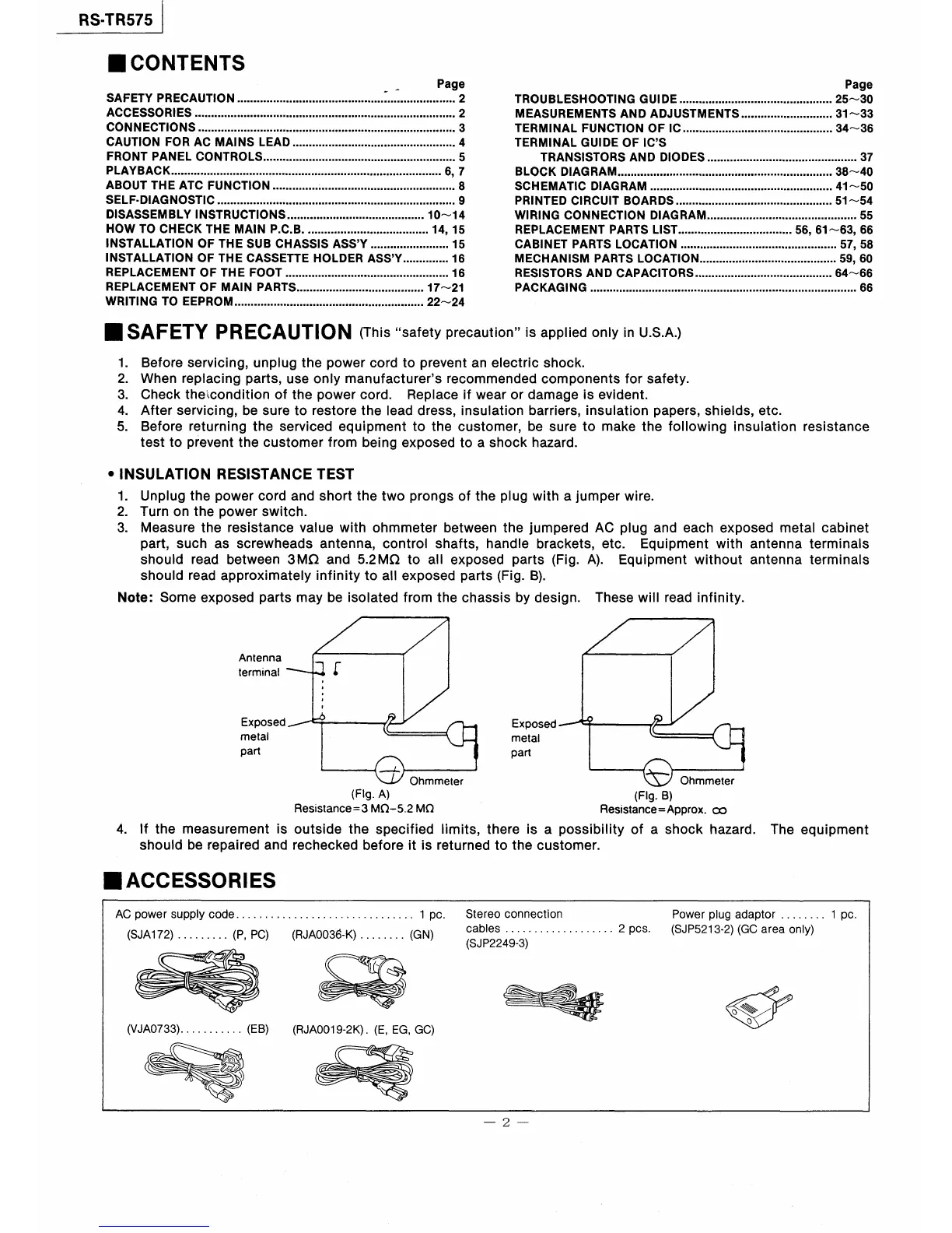
●lNSUIATION RESISTANCE TEST
1.Unplug the powercord and short the two prongs of the plug with ajumperwire.
2.Tum on the power switch.
3.Measure the resistance value with ohmmeter between the jumpered AC plug and each exposed metal cabinet
part,such as screwheads antenna,control shafts,handle brackets,etc. Equipment with antenna terminals
should read between3MΩand5。2MΩto aexposed parts(Fig.A). Equipment without antenna terminals
should read approximately infinity to all exposed parts(Fig、B).
Note=Some exposed parts may be isolated from the chassis by design. These will read infinity.
4.
Antenna
termlnal
Exposed
meヒaI
part
繍
Exposed
metal
part
Ohmmeter Ohmmeter
(Fl9・A) (Fl9.B》
Reslstance=3MΩ一5.2MΩ Resistance=Approx。oo
lf the measurement is outside the specified Iimits,there is a possibility of a shock hazard.
should be repaired and rechecked before it ls retumed to the customer.
The equipment
■ACCESSORlES
AC power supPly code.
(SJA172)
7
(P,PC) (RJAOO36−K)
ノ ク{
1pc.
(GN)
Stereo connection
cables ...
(SJP2249−3)
2pcs.
Power plug adaptor..... 1pc.
(SJP5213・2)(GC area only)
(VJAO733).
駅
眠 。
o
\
h
∠
㊦
(EB) (RJAOO19−2K).(E,EG,GC)
2
 Loading...