RS・TR575
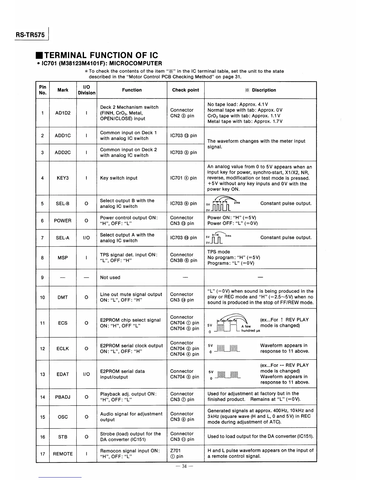
■TERMINAL FUNCTION OF IC
●IC701(M38123M4101F》=MICROCOMPUTER
*To checkthe conteハts of the item※in the IC terminal tabIe,set the unit to the state
described in theMotorControl PCB Checking Methodon page31.
Pin
No.
Mark
1O
Division
Function
Check poin量
※Disc巾量ion
1
ADI D2
1
Deck2Mechanism switch
(FINH,CrO2,Metal,
OPEN,CLOSE)input
Connector
CN2③pin
No tape Ioad:ApProx.4.1V
Normal tape with tab:Approx.OV
CrO2tape with tab:Approx.1.1V
Metal tapewith tab:Approx.1,7V
2
ADDIC
1
Common input on Deck l
with analog IC switch
lC703⑬pln
The waveform changes with the meter input
signal.
3
ADD2C
1
Common input on Deck2
with analog IC switch
lC703③pin
4
KEY3
1
Key switch input
IC701④pin
An analog value from O to5V appears when an
input key for power,synchro・start,XI IX2,NR,
reverse,modification or test mode is pressed.
十5V without any key inputs and OV with the
power key ON.
5
SEL・B
0
Select output B with the
analog IC swltch
IC703⑨pin
門『H 2ms Constantpulseoutput.
1コ㎜
6
POWER
0
Power control output ON:
H,OFF:L
Connector
CN3⑬pin
Power ON:H(=5V)
Power OFF=L(=OV)
7
SEL−A
110
Select output A with the
anaIog IC switch
lC703⑩pin
へ
ト』輔 4ms
ll皿, Constantpulseoutput・
8
MSP
1
TPS signal det.input ON:
L,OFF:H
Connector
CN3B⑧pin
TPS mode
No program:H(=5V)
Programs:L(ニOV)
9
一 一
Not used
一
一
10
DMT
O
Lineout mutesignal output
ON=L,OFF:H
Connector
CN3⑭pin
L(=OV)when sound is belng produced in the
play or REC mode andH(=2.5〜5V)when no
sound is produced ln the stop of FFlREW mode.
11
ECS
O
E2PROM chip select signaI
ON:H,OFFL
Connector
CN704①pin
CN704⑤pin
論 (ex…F・r↑REVPLAY
5」」㎜ゴr一艦,d、、modeischanged)
12
ECLK
O
E2PROM serial clock output
ON:L,OFF=H
Connector
CN704②pin
CN704④pin
5」」旧llllL 鵠潔,ε鵯e搬.
13
EDAT
110
E2PROM serial data
input/output
Connector
CN704③pin
(ex_For⇔REV PLAY
5」」旧IllL 朧f謡h辮s、n
response to ll above。
14
PBADJ
O
Playback adj.output ON=
H,OFF:L
Connector
CN3⑦pin
Used for adjustment at factory but in the
finished product. Remains atL(=OV)。
15
OSC
O
Audio signal for adjustment
output
Connector
CN3⑥pin
Generated signals at approx.400Hz,10kHz and
3kHz(square wave(H and L,O and5V)in REC
mode during adlustment of ATC)。
16
STB
O
Strobe(bad)output for the
DA converter(IC151)
Connector
CN3⑪pin
Used to Ioad output for the DA converter(IC151).
17
REMOTE
1
Remocon signal input ON:
H,OFF:L
Z701
①pin
H and L pulse waveform appears on the input of
a remOte COntrd Signal,
一34一
 Loading...