SA-110
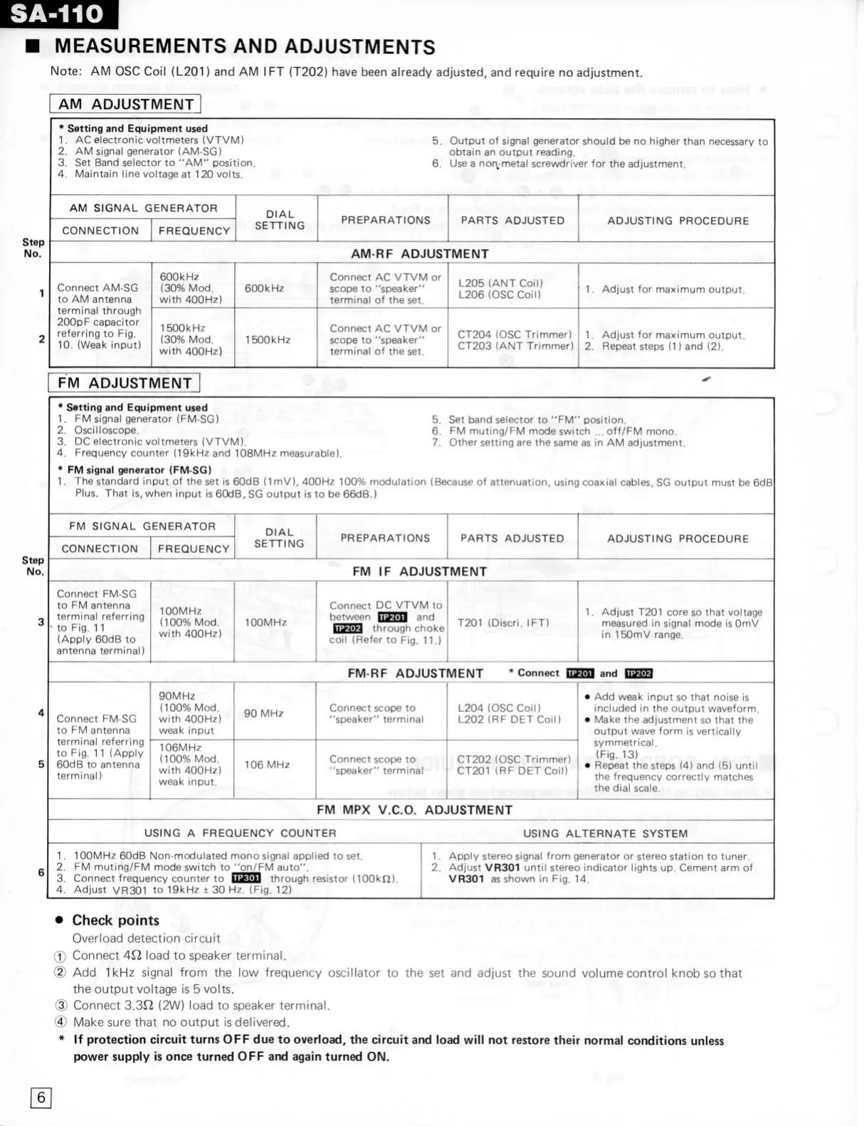
MEASUREMENTS
AND
ADJUSTMENTS
Note:
AM OSC
Coil {L201)
and AM I FT
(T202) have been already adjusted,
and
require
no
adjustment.
AM
ADJUSTMENT
* Setting
and
Equipment used
1.
AC
electronic voltmeters (VTVM)
. 5,
Output
of
signal generator shouid
be no
higher than necessary
to
2.
AM
signal generator (AM-SG) obtain
an
output reading.
3.
Set
Band selector
to
"AM"
position.
6.
Use
a
non-metal screwdrjver
for the
adjustment.
4.
Maintain line voltage
at
1
20
volts.
AM
SIGNAL GENERATOR
DIAL
SETTING
PREPARATIONS PARTS ADJUSTED
ADJUSTING PROCEDURE
CONNECTION FREQUENCY
DIAL
SETTING
PREPARATIONS PARTS ADJUSTED
ADJUSTING PROCEDURE
AM-RF ADJUSTMENT
Connect AM-SG
to
AM
antenna
terminal through
200pF capacitor
referring
to Fig.
10.
(Weak input)
600kHz
(30%
Mod.
with 400H2)
600kHz
Connect
AC
VTVM
or
scope
to
"speaker"
terminal
of the set.
L205
(ANT
Coil)
L206
(OSC
Coil)
1.
Adjust
for
maximum output.
Connect AM-SG
to
AM
antenna
terminal through
200pF capacitor
referring
to Fig.
10.
(Weak input)
1500kHz
(30%
Mod.
with 400Hz)
1500kHz
Connect
AC
VTVM
or
scope
to
"speaker"
terminal
of the set.
CT204
(OSC
Trimmer)
CT203
(ANT
Trimmer)
1.
Adjust
for
maximum output.
2.
Repeat steps
(1) and (2).
FM
ADJUSTMENT
5.
Set
band selector
to
"FM"
position.
6.
FM
muting/FM mode switch
...
off/FM mono.
7. Other setting
are the
same
as in AM
adjustment.
* Setting
and
Equipment used
1.
FM
signal generator (FM-SG)
. » ...
2.
Oscilloscope.
3.
DC
electronic voltmeters (VTVM).
4.
Frequency counter (19kHz
and
108MHz measurable).
*
FIV1
signal generator (FM-SG)
1.
The
Standard
input
of
the
set is
60dB
(1
mV), 400Hz
100%
modulation (Because
of
attenuation, using coaxial cables,
SG
output must
be 6dB
Plus.
That
is,
when input
is
60dB,
SG
output
is to be
66dB.)
FM SIGNAL GENERATOR
DIAL
SETTING
PREPARATIONS PARTS ADJUSTED
ADJUSTING PROCEDURE
CONNECTION
FREQUENCY
DIAL
SETTING
PREPARATIONS PARTS ADJUSTED
ADJUSTING PROCEDURE
FM
IF
ADJUSTMENT
Connect FM-SG
to
FM
antenna
terminal referring
to
Fig.
11
(Apply 60dB
to
antenna terminal)
100MHz
(100%
Mod.
with 400Hz)
100MHz
Connect
DC
VTVM
to
between tOïTïn
and
iJMM through choke
coil (Refer
to Fig. 11.)
T201 (Discri.
IFT)
1.
Adjust
T201
core
so
that voltage
measured
in
signal mode
is
OmV
in
1
50mV range.
FM-RF ADJUSTMENT *
Connect
and Qü^
Connect FM-SG
to
FM
antenna
terminal referring
to
Fig.
11
(Apply
60dB
to
antenna
terminal)
90MHz
(100%
Mod.
with 400Hz)
weak input
90
MHz
Connect scope
to
"speaker" terminal
L204
(OSC
Coil)
L202
(RF DET
Coil)
•
Add
weak input
so
that noise
is
included
in the
output waveform.
• Make
the
adjustment
so
that
the
output wave form
is
vertically
symmetrical.
(Fig.
13)
• Repeat
the
steps
(4) and (5)
until
the frequency correctly matches
the dial scale.
Connect FM-SG
to
FM
antenna
terminal referring
to
Fig.
11
(Apply
60dB
to
antenna
terminal)
106MHz
(100%
Mod.
with 400Hz)
weak input.
106
MHz
Connect scope
to
"speaker" termina
CT202
(OSC
Trimmer)
CT201
(RF DET
Coil)
•
Add
weak input
so
that noise
is
included
in the
output waveform.
• Make
the
adjustment
so
that
the
output wave form
is
vertically
symmetrical.
(Fig.
13)
• Repeat
the
steps
(4) and (5)
until
the frequency correctly matches
the dial scale.
FM MPX
V.C.0.
ADJUSTMENT
USING
A
FREQUENCY COUNTER USING ALTERNATE SYSTEM
1.
1
OOMHz 60dB Non-modulated mono signal applied
to set.
2.
FM
muting/FM mode switch
to
"on/FM auto".
3. Connect frequency counter
to
mtOU through resistor
(lOOkn).
4.
Adjust VR301
to
19kHz
± 30 Hz. (Fig. 12)
1.
Apply stereo signal from generator
or
stereo station
to
tuner.
2.
Adjust VR301 until stereo indicator lights
up.
Cement
arm
of
VR301
as
shown
in Fig. 14.
•
Check points
Overload detection circuit
•''
0
Connect
4^
load
to
speaker terminal.
(2)
Add 1kHz
signal from
the low
frequency oscillator
to the set and
adjust
the
sound volume control knob
so
that
the output voltage
is 5
volts.
(3) Connect
3.3Q, (2W)
load
to
speaker terminal.
® Make sure that
no
output
is
delivered.
*
If
protection circuit turns
OFF due to
overload,
the
circuit
and
load will
not
restore their normal conditions uniess
power suppiy
is
once turned
OFF and
again turned
ON.
6
 Loading...