EasyManuals Logo
Home>Technics>Turntable>SL-1900

Technics SL-1900 User Manual

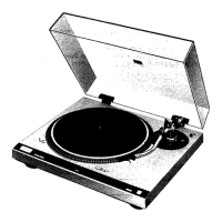
Technics SL-1900
12 pages
To Next Page IconTo Next Page
To Previous Page IconTo Previous Page
Page #2 background imageLoading...
Page #2 background image
@
Phono
cables
@Output
terminals
Parts
identification
It
@AC
power
prus
@
Ground
wire
O
Hinge
€)
Turntable
mat
O
Turntable
Platter
@
Motor
shaft
(Center sPindle)
@
Strobe
mark
O
Strobe
illuminator/
pilot
O
Strobe
dots
@
Speed
selector
we
want
to
thank
you
for
selecting
the
sL-1900,
Direct
Drive
Automatic
Turntable
system'
For
optimum
performance,
we
recommend
that
you
read
these
instructions
carefully'
cautiont
Never
connectthe
Ac
power
plug
before
the
assembly
has been
completed'
Assembly
and
set-up
The operating
instructions
are
commonly
applicable
to sets
with
cartridge
and
without
cartridge,
so
that
please
refer
to
the
following
notes
for further
information.
Since
the overhang
gauge
is
furnished
to sets
without
cartridge,
refer
to
the
item
concerning
cartridge
installation
for
correct
mounting.
For sets
without
cartridge,
the
cartridge
section
of the
specifica-
tions
may
be
neglected'
@
Balance
weight
€D
Stylus
pressure ring
@
Anti-skating
control
knob
@
Arm
rest
@
Cueing
lever
(D
Arm
clamp
@Memo-repeat
(9
Tubular
arm
@
Record
size
selector
nut
@Start/stop
lever
(D
Head
shell/cartridge
@
Turntable
base
€l
Pitch control
knobs
500
hours),
so
do
not
apply
too
much
oil,
nor
more
frequently
than
necessary.
Never
use
any
other
type
of
oil'
€)lnstallation
of
the turntable
platter
1.
Place
the
turntable
platter
on
the
motor
shaft
(center spindle)'
2.
Place
the
turntable
mat on
the
platter'
Note:
1)
The
rotor
is connected
to
the
reverse
surface
of
the turn-
table
platter. (The
magnet
of
the
motor
is attached
to
the
turntable
platter.)
To
maintain
optimum
performance as
soecified,
extra
care
should
be taken
to
prevent
adhesion
of
dust
or
iron
filings
to
the magnet
and
not
to damage
the
magnet
bY
droPPing
it'
2)
Do
not
remove
the
three
screws
for securing
the
magnet'
(See
Fig.
3.)
Should
the
position
ol
the
f ixed
magnet
be
altered
by
loosening
the
securing
screws,
the rated
performance of
the unit
can
not
be
guaranteed.
@lnstallation
of
the
head
shell
(See
Fig'
a')
Insert
the
plug
portion
of
the
head
shell
into
the tront
end
of
the tubular
arm,
and
turn
the
locking
nut clockwise
(in
the
direction
shown
by
the
arrow
"A"),
with
the
head
shell
held
horizontally
to secure
JirmlY.
QCheck
the
Paris.
Turntable
unit
. ........
Turntable
Platter
... ..
Turntable
mat
.....
..
Dust cover
45
r.p.m.
adaptor
Special
oi1.
.......
Balance
weight
Head
shell/cartridge
...
...
(Overhang
gauge
....1
...1
....1
...1
1
1
1
1
..1)
gApply
two
or
three
drops
of oil
to
the
molor
shalt
using
the
furnished
oil
container'
(See
Fig. 2.)
Although
the
unit
has been
lubricated
before
shipping
from
the
{actory,
apply
a few drops
of oil
to
the
motor
sha{t
for assur-
ance.
After
that,
application
of
two
or
three
drops
o{ oil
once
every
2000
hours'
operation
or so
is sufiicient'
The
time
in-
terval
is
much.
longer
than
that
of
the
former
type
motors
(200-

Other manuals for Technics SL-1900

Questions and Answers:

Question and Answer IconNeed help?

Do you have a question about the Technics SL-1900 and is the answer not in the manual?

Technics SL-1900 Specifications

General IconGeneral
BrandTechnics
ModelSL-1900
CategoryTurntable
LanguageEnglish

Related product manuals