EasyManua.ls Logo

TECO JSDAP-15A User Manual

TECO JSDAP-15A
255 pages
To Next Page IconTo Next Page
To Previous Page IconTo Previous Page
Page #144 background image
5-58
5-5-1 Automatic Gain Adjustment
This device provides ON-LINE Auto tuning, which can quickly and precisely measure Load Inertia and
adjust the Gain automatically. Setting is according to the table below:
Parameter Name Setting Description
Control
Mode
0 Auto tuning Disabled
Cn002.2
Auto tuning
1 Enable Auto tuning
Pe/Pi/S
When Cn002.2 is set to 0 (Auto tuning Disabled), following Gain adjust parameters must be set.
Parameter
Signal
Name
Cn025 Load Inertia Ratio
Sn211 Speed Loop Gain 1
Sn212 Speed-loop Integral time constant 1
Sn213 Speed loop Gain 2
Sn214 Speed loop Integral time constant 2
Pn310 Position Loop Gain 1
Pn311 Position Loop Gain 2
Pn312 Position Loop Feed-Forward Gain
When Cn002.2 is set to 1 auto tuning is enabled and the Servo controller will adjust the Servo Gain in
accordance with Cn026 (Rigidity Setting) and the measured Load Inertia Ratio by monitor parameter
Un-19 (Load Inertia Ratio), when the Load Inertia Ratio is becomes stable,
Then set 0 in Cn002.2 to cancel Auto tuning. At this moment, servo controller will record the measured
Load Inertia Ratio into Cn025 (Load Inertia Ratio).
If servo drive is used in a applications where there is no significant load variations, then monitor Un-19
(Load Inertia Ratio) if this is stable then it is recommended that Auto tuning is not used.

Table of Contents

Question and Answer IconNeed help?

Do you have a question about the TECO JSDAP-15A and is the answer not in the manual?

TECO JSDAP-15A Specifications

General IconGeneral
ModelJSDAP-15A
CategoryServo Drives
Rated Output Current15A
Applicable Motor Capacity1.5kW
Rated Output Power1.5kW
Input Voltage200-230V AC
Control ModePosition, Speed, Torque
Communication InterfaceRS-485
Power Supply200-230V AC
FeedbackEncoder
Protection FeaturesOvercurrent, Overvoltage, Overheating

Summary

Essential Safety Information

Warnings and Cautions

Critical warnings and precautions for safe operation and installation of the servo drive.

Chapter 1 Checking and Installing

Introduction to Servo Drive Operation Modes

Chapter 2 Wiring and Connections

Basic Servo System Wiring Overview

Fundamental principles and diagrams for correctly wiring the servo system components.

Servo Drive Wiring Precautions

Critical instructions and safety measures for wiring the servo drives accurately.

Chapter 3 Panel Operator Interface

Chapter 4 Trial Operation Procedures

Chapter 5 Control Functions

5-1 Control Mode Selection

Guide to selecting operational modes like Torque, Speed, and Position control.

5-2 Torque Mode Operation

Configuration and adjustment of parameters related to Torque control functions.

5-5 Gain Adjustment Procedures

Methods for adjusting servo system gains to optimize performance and stability.

Chapter 6 Parameter Reference

Parameter Group Explanations

Classification and explanation of the different parameter groups within the drive.

System Parameter Details

Detailed table of essential system parameters for drive configuration.

Chapter 7 Communications Functionality

Chapter 8 Troubleshooting Guide

Alarm Functions and Status Interpretation

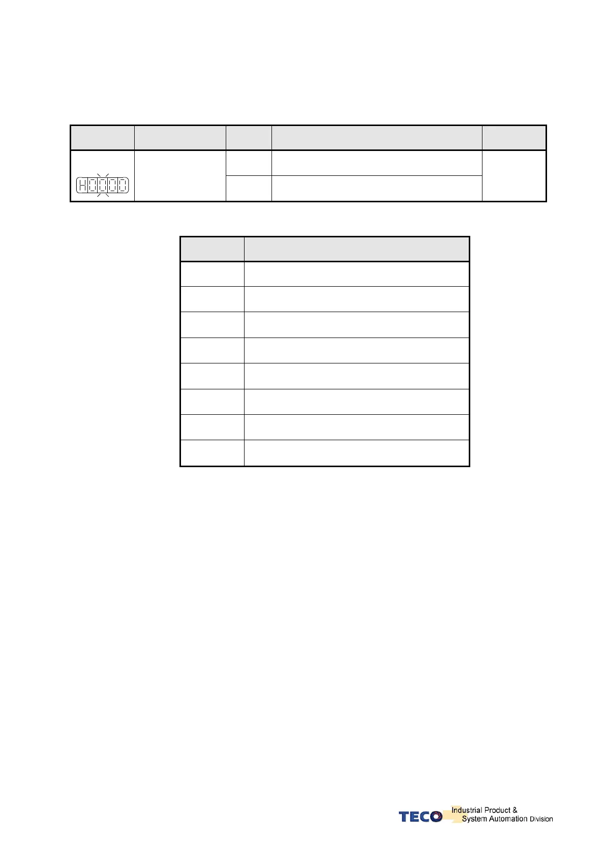
Explanation of alarm codes, their meanings, and how to interpret status displays.

Chapter 9 Specifications

Related product manuals