EasyManuals Logo
Home>Tektronix>Test Equipment>2205

Tektronix 2205 Operator's Manual

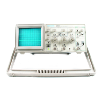
Tektronix 2205
94 pages
To Next Page IconTo Next Page
To Previous Page IconTo Previous Page
Page #32 background imageLoading...
Page #32 background image
Operation
LEARNING
THE
CONTROLS
If
you
have
not
read
Section
1
yet,
you
should
do
so
now.
Then,
after
turning
the
power
on,
let
the
oscilloscope
warm
up
for
a
few
minutes
before
starting
this
procedure.
1.
S
et
instrument
controls
as
follows:
Display
INTENSITY
FOCUS
Vertical
(both
channels)
POSITION
MODE
VOLTS/DIV
VOLTS/DIV
Varible
Input
Coupling
Midrange
Set
for
clearly
defined
trace
Midrange
CH
1
.1
V
(iX)
CAL
detent
(fully
clockwise)
AC
Horizontal
POSITION
MODE
SEC/DIV
SEC/DiV
Variable
Midrange
X1
0.2
ms
CAL
detent
(fully
clockwise)
Trigger
SLOPE
LEVEL
MODE
SOURCE
2.
Connect
a
signal
adapter
to
the
Channel
1
input
BNC
con¬
nector
(labeled
CH
1
or
X).
Attach
the
ground
lead
to
the
collar
of
the
EXT
INPUT
connector
and
apply
the
signal
adapter
tip
to
the
PROBE
ADJUST
terminal.
If
necessary,
adjust
the
TRIGGER
LEVEL
control
to
get
a
stable
display.
3.
Change
the
Channel
1
input
coupling
to
GND
and
use
the
Channel
1
POSITION
control
to
align
the
baseline
trace
to
the
Midrange
P~P
AUTO
CH
1
2-6
2205
Operator’s

Other manuals for Tektronix 2205

Questions and Answers:

Question and Answer IconNeed help?

Do you have a question about the Tektronix 2205 and is the answer not in the manual?

Tektronix 2205 Specifications

General IconGeneral
BrandTektronix
Model2205
CategoryTest Equipment
LanguageEnglish

Related product manuals