Performance Check—2465B/2467B Service
k. CHECK—Signal display amplitude is 1.9 to 2.1
divisions.
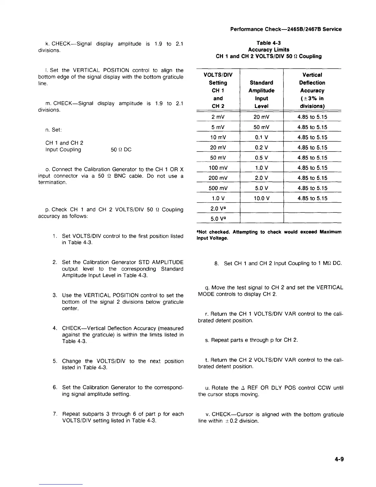
Table 4-3
Accuracy Limits
CH 1 and CH 2 VOLTS/DIV 50 fi Coupling
I. Set the VERTICAL POSITION control to align the
bottom edge of the signal display with the bottom graticule
line.
m. CHECK—Signal display amplitude is 1.9 to 2.1
divisions.
n. Set:
CH 1 and CH 2
Input Coupling
50 fi DC
o. Connect the Calibration Generator to the CH 1 OR X
input connector via a 50 S! BNC cable. Do not use a
termination.
p. Check CH 1 and CH 2 VOLTS/DIV 50 Q Coupling
accuracy as follows:
1.
Set VOLTS/DIV control to the first position listed
in Table 4-3.
VOLTS/DIV
Setting
CH 1
and
CH 2
2mV
5 mV
10 mV
20 mV
50 mV
100 mV
200 mV
500 mV
1.0 V
2.0 V
a
5.0 V
a
Standard
Amplitude
Input
Level
20 mV
50 mV
0.1 V
0.2 V
0.5 V
1.0 V
2.0 V
5.0 V
10.0 V
Vertical
Deflection
Accuracy
(±3%
in
divisions)
4.85 to 5.15
4.85 to 5.15
4.85 to 5.15
4.85 to 5.15
4.85 to 5.15
4.85 to 5.15
4.85 to 5.15
4.85 to 5.15
4.85 to 5.15
"Not checked. Attempting to check
Input Voltage.
would exceed Maximum
2.
Set the Calibration Generator STD AMPLITUDE
output level to the corresponding Standard
Amplitude Input Level in Table 4-3.
3. Use the VERTICAL POSITION control to set the
bottom of the signal 2 divisions below graticule
center.
4.
CHECK—Vertical Deflection Accuracy (measured
against the graticule) is within the limits listed in
Table 4-3.
8. Set CH 1 and CH 2 Input Coupling to 1 Mfi DC.
q.
Move the test signal to CH 2 and set the VERTICAL
MODE controls to display CH 2.
r. Return the CH 1 VOLTS/DIV VAR control to the
cali-
brated detent position.
s. Repeat parts e through p for CH 2.
5. Change the VOLTS/DIV to the next position
listed in Table 4-3.
t. Return the CH 2 VOLTS/DIV VAR control to the
cali-
brated detent position.
6. Set the Calibration Generator to the correspond-
ing signal amplitude setting.
u.
Rotate the A REF OR DLY POS control CCW until
the cursor stops moving.
7. Repeat subparts 3 through 6 of part p for each
VOLTS/DIV setting listed in Table 4-3.
v. CHECK—Cursor is aligned with the bottom graticule
line within ±0.2 division.
4-9
 Loading...


